
More project photos (2)
The problem
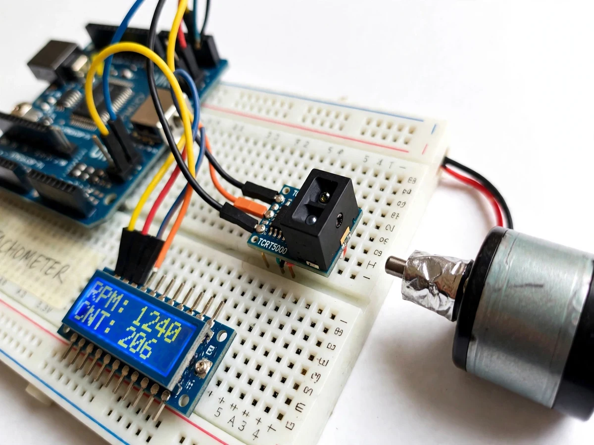
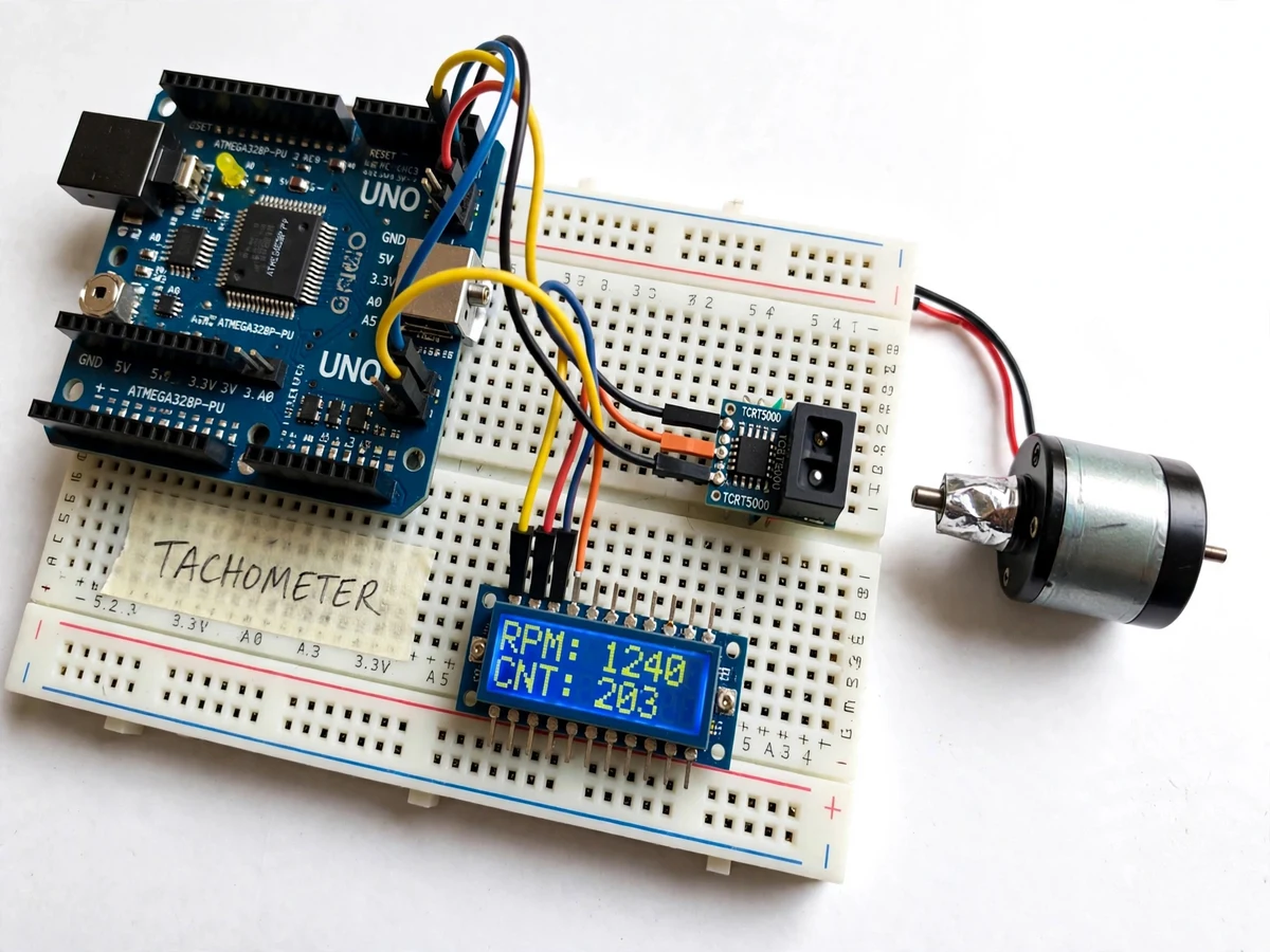
Motor speed is one of the most basic quantities in electrical and electronics work, yet most students have no way to measure it without touching the spinning shaft. A digital tachometer with an optical sensor solves this by reading speed contactlessly: a small reflective marker on the shaft flashes past a light sensor once per revolution, and the electronics convert those flashes into revolutions per minute. The problem this project addresses is practical. Workshop motors, fans, pumps and small drives are routinely run at unknown speeds, and guessing from the supply voltage or the sound of the motor tells the user almost nothing reliable. Handheld tachometers exist, but they are an extra instrument to buy, and they teach nothing about how the measurement itself works. This project closes that gap by building the instrument from parts a student already owns: an Arduino Uno, a TCRT5000 reflective optical sensor module, a 16x2 LCD and a small DC motor.
Spins the shaft carrying one strip of reflective tape.
Follow the working sequence
How it works
The measurement runs as a short chain from shaft to display. A strip of reflective tape on the motor shaft passes in front of the TCRT5000 reflective optical sensor once every revolution. The sensor's infrared LED shines light at the shaft and its phototransistor watches for the reflection: the bright tape throws back far more infrared light than the dark shaft, so the sensor output flips each time the marker passes. That flip is wired to digital pin 2 of the Arduino Uno, where a hardware interrupt increments a pulse counter the instant it happens, without waiting for the main program loop. Once a second, the program reads the counter, applies the formula RPM equals pulses per minute divided by markers per revolution, and writes the result to the 16x2 LCD. With one marker fitted, the formula reduces to pulses per second multiplied by 60, so the displayed number is the shaft speed in revolutions per minute.
- A strip of reflective tape is stuck flat on the motor shaft or hub, with the surrounding shaft surface left dark so the marker stands out.
- The TCRT5000 reflective optical sensor module is mounted 5–10 mm from the shaft (design target gap), facing the path of the tape.
- The sensor output is wired to digital pin 2 of the Arduino Uno, the module is powered from 5 V, and the 16x2 LCD is connected through its I2C adapter.
- Each time the tape passes, the sensor output flips and a hardware interrupt increments a pulse counter immediately.
- Once every second the program reads the counter, computes RPM as pulses per minute divided by markers per revolution, and resets the counter for the next interval.
- The RPM value and the running pulse total are written to the 16x2 LCD and printed to the serial monitor.
- The builder verifies the reading by hand-turning the shaft a known number of revolutions and checking that the pulse total matches.
Tech stack:
- Arduino Uno (ATmega328P)
- TCRT5000 reflective optical sensor
- 16x2 LCD · I2C adapter
- Arduino IDE
- Embedded C · C++
- DC motor · reflective tape marker
- Breadboard · jumper wires
- 5 V DC power supply
| Parameter | Value |
|---|---|
| Controller | Arduino Uno, ATmega328P, 16 MHz clock (datasheet value) |
| Sensor | TCRT5000 reflective optical sensor module, 950 nm infrared LED (datasheet value) |
| Display | 16x2 LCD with I2C adapter |
| RPM display range | 0–9,999 RPM (design target) |
| Resolution | 1 RPM (design target) |
| Accuracy | ±1% of reading (design target, not a measured result) |
| Sensor-to-shaft gap | 5–10 mm (design target) |
| Update interval | 1 second (design target) |
| Demo motor | 6–12 V DC motor (typical demo motor) |
| Supply | 5 V DC via USB or adapter |
Project features
The strongest parts of this build are its sensing method, its counting method and its live display. First, the reflective optical sensor reads speed without touching the shaft, so nothing loads the motor and nothing wears out. Second, every pulse is counted by a hardware interrupt on the Arduino Uno, so the count keeps up even while the display is being updated. Third, the 16x2 LCD shows the speed live in RPM together with a running pulse total, so the result is visible the moment the motor spins. Fourth, the sensor threshold is adjustable with the onboard potentiometer, which lets the builder tune the detection point for different shaft colours and room lighting. Together these four capabilities make a compact instrument that is simple to build, easy to explain in a review, and genuinely useful for checking the speed of small DC motors, fans and model drives.
- [Reflective optical sensing] A TCRT5000 module shines infrared light at the shaft and watches the reflection, so speed is read without any contact, coupling or loading on the motor.
- [Interrupt-based pulse counting] The sensor output feeds digital pin 2 of the Arduino Uno, where a hardware interrupt increments the pulse counter the instant each marker passes, so no pulse is missed while the display updates.
- [Live RPM display on 16x2 LCD] The current speed is shown in revolutions per minute on a 16x2 LCD, refreshed once every second, with the running pulse total on the second line.
- [Running pulse total] The LCD also shows the total number of marker passes counted since switch-on, which makes it easy to verify the counting against hand-turned revolutions.
- [Adjustable detection threshold] The onboard potentiometer sets the point at which the sensor trips, so the builder can tune the module for different shaft colours, tape types and room lighting.
- [Non-contact measurement] Nothing touches the rotating shaft, so the measurement adds no friction, needs no coupling, and works on any shaft that can carry a small reflective marker.
- [Serial monitor output] The same RPM value is printed to the Arduino serial monitor, so readings can be watched on a laptop and checked against the LCD during testing.
What is included
- Working prototype: Arduino Uno, TCRT5000 sensor module, 16x2 LCD, DC motor with reflective tape marker, breadboard wiring
- Arduino firmware source code with interrupt-based pulse counting and LCD display
- Circuit and wiring documentation
- Component list with part names
- Setup and sensor-calibration instructions
- Project abstract PDF
- Demonstration guidance for the review
Limitations & prerequisites
- Accuracy of ±1% of reading is a design target, not a measured result — verify the reading against a known reference before quoting it in a report.
- Strong ambient light, especially sunlight and fluorescent flicker, can false-trigger the sensor; shade the sensor head and adjust the threshold potentiometer in bright rooms.
- The reflective tape must sit flat and flush on the shaft — a curled or lifting edge can produce two pulses from one pass, as found during the demo build.
- The build uses one marker per revolution; fitting more markers needs the RPM formula changed to divide by the marker count.
- There is no SD-card data logging in this build; readings are live on the LCD and serial monitor only.
- The prototype is designed for small DC motors, fans and model drives, not for large or very high-speed industrial shafts.
- The LCD refreshes once per second (design target), so a rapidly changing speed lags the display by up to one interval.
Frequently Asked Questions
Is this project suitable for a final-year project?
Yes. This project suits final-year students in Electronics & Telecommunication, Electrical and Electronics Engineering because it combines a real sensing problem with embedded programming and a working instrument as the outcome. It demonstrates reflective optical sensing, hardware interrupts, pulse counting and LCD interfacing — four distinct concepts a review panel can question the student on. The build is compact enough to complete and demonstrate within a semester, and it leaves the student with a reusable measurement tool for later motor experiments.
How does the reflective optical sensor detect the shaft speed?
The TCRT5000 module shines infrared light from a 950 nm LED at the shaft and watches the reflection with a phototransistor. A strip of reflective tape on the shaft throws back far more infrared light than the dark shaft surface, so the sensor output flips once per revolution as the tape passes. The Arduino counts those flips and converts them into RPM. Because the sensing is optical, nothing touches the shaft and the motor is never loaded by the measurement.
What is the RPM range and accuracy of this tachometer?
The display is designed for 0 to 9,999 RPM with 1 RPM resolution, and the accuracy is a design target of ±1% of reading — not a measured result. The practical range depends on the motor used and on clean sensor triggering, and the demo motor runs well inside this range. Accuracy should be checked against a known reference, such as a second tachometer, before the reading is quoted in a report. Very high speeds can outrun the phototransistor response, so the design target assumes small DC motors.
Does this tachometer store or log RPM readings?
No. This build shows the speed live on its 16x2 LCD and through the Arduino serial monitor, and it keeps no record once the power is off. There is no SD card and no data logging in this version, which is what sets it apart from tachometer builds that add logging hardware. If logged readings are needed, an SD-card module can be added as a customization. The live display suits bench checks and demonstrations, where the current speed is what matters.
Can the tachometer measure the speed of other motors or fans?
Yes, within limits. Any rotating shaft or fan hub that can carry a small flat strip of reflective tape can be measured, provided the sensor can be held 5 to 10 mm from the marker and the shaft surface around it stays dark. The marker must sit flat and the tape edge must not lift, or one pass can produce two pulses. Large or very fast industrial shafts are outside this prototype's scope. The same sensor head works on fans, model drives and small pumps.
What power supply does the prototype need?
The prototype runs from a 5 V DC supply, either the Arduino Uno's USB connection or a 5 V adapter, which also powers the sensor module and the LCD. The demo DC motor needs its own supply matched to its rating, typically 6 to 12 V, and must not be driven directly from the Arduino pins. A separate motor supply keeps the sensor readings stable when the motor draws current. A common ground between the motor supply and the Arduino is required.
Components & software requirements
- Arduino Uno (ATmega328P)
- TCRT5000 reflective optical sensor
- 16x2 LCD · I2C adapter
- Arduino IDE
- Embedded C · C++
- DC motor · reflective tape marker
- Breadboard · jumper wires
- 5 V DC power supply
Delivery information
Built-to-order project. Delivery timeline is shared after order confirmation based on current queue.
Support terms
Complete documentation, setup guide, and viva preparation included. Support for setup and explanation provided.
Download free synopsis (PDF)
Enter your name and WhatsApp number — the synopsis PDF downloads immediately. We may send occasional project updates on WhatsApp; no spam.