
More project photos (2)
The problem
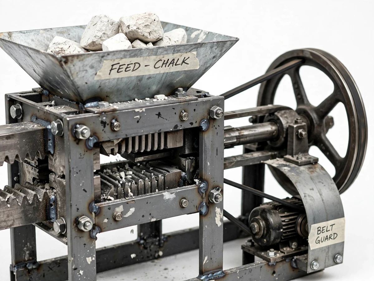
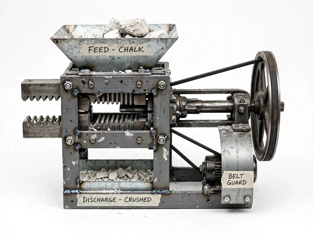
Primary crushing — breaking run-of-mine rock down to handleable size — starts with the jaw crusher in almost every mineral-processing flowsheet, yet students usually meet it only as a cross-section diagram with the eccentric, toggle plate and jaw dies labelled. This project fabricates a working bench-scale jaw crusher: a fixed jaw die bolted to the frame, a swing jaw pivoted at the top and driven at the bottom by an eccentric shaft through a toggle plate, a flywheel to smooth the crushing stroke, a V-belt drive from a single-phase motor, a feed hopper and an adjustable closed-side setting. The student feeds chalk lumps, charcoal or soft brick pieces, collects the crushed product, sieves both feed and product, and computes the reduction ratio and the product size distribution from their own weighings. The nip angle, the stroke and the toggle action stop being diagram labels and become things the student has watched work.
How it works
- Set the closed-side discharge gap with the wedge/shim adjustment and record the setting.
- Start the motor and let the crusher reach steady speed; observe the swing jaw's stroke at the discharge end.
- Feed chalk lumps, charcoal or brick pieces steadily through the hopper — the corrugated jaws nip and crush each piece on the closing stroke.
- Collect the crushed product from the discharge and sieve both a feed sample and the product through the test sieve set.
- Weigh each sieve fraction and determine the 80%-passing sizes of feed (F80) and product (P80) from your weighings.
- Compute the reduction ratio as F80 ÷ P80 and plot the product size distribution.
- Repeat at a different closed-side setting and show how the product curve follows the gap — from your own data.
Tech stack:
- Fixed and swing jaw dies (replaceable)
- Eccentric shaft with bearings
- Toggle plate assembly
- Cast flywheel
- Single-phase motor with V-belt drive
- Feed hopper and discharge chute
- Closed-side-setting wedge adjustment
- Test sieve set and digital weighing scale
| Parameter | Value |
|---|---|
| Feed opening | Approximately 150 × 100 mm (design target) |
| Eccentric stroke | Approximately 10–15 mm at the jaw bottom (design target) |
| Closed-side setting | Adjustable, approximately 10–25 mm (design target) |
| Drive | Single-phase motor, approximately 1 HP with V-belt (design target) |
| Flywheel | Cast, sized for the stroke (design target) |
| Feed materials | Chalk, charcoal, soft brick pieces (crushable, non-abrasive) |
| Reduction ratio | Student-measured from sieve analysis (F80/P80) |
| Overall size | Approximately 700 × 500 × 900 mm (approximate) |
Project features
- [Fixed and swing jaw dies] Replaceable manganese-steel-profile jaw plates (or hardened MS for the model) with a corrugated crushing face for positive nipping.
- [Eccentric shaft drive] A machined eccentric shaft gives the swing jaw its horizontal crushing stroke at the bottom while the top pivots — the defining jaw-crusher motion.
- [Toggle plate] The toggle transmits the eccentric's motion to the swing jaw and doubles as the mechanical overload release.
- [Flywheel] A cast flywheel smooths the intermittent crushing load so the motor sees a steadier torque.
- [Adjustable closed-side setting] Wedge or shim adjustment of the discharge gap lets the student test how the product size follows the setting.
- [Feed hopper] A sheet-metal hopper guides feed into the crushing chamber and keeps the crushing zone guarded.
- [Belt drive with guard] V-belt drive from a single-phase motor with a full belt guard for safe student operation.
- [Reduction ratio from your sieves] Feed and product are sieve-analysed by the student; the reduction ratio is computed from measured sizes, not assumed.
What is included
- Fabricated jaw crusher: frame, jaws, eccentric shaft, toggle, flywheel
- Single-phase motor with V-belt drive and belt guard
- Feed hopper and discharge chute
- Replaceable jaw die set
- Test sieve set and digital weighing scale
- Feed material starter pack (chalk/brick pieces)
- Trial procedure and observation sheets (blank, for your weighings)
- Project report PDF (crushing theory, design, procedure)
- PPT presentation for final review
- Viva Q&A preparation document
Limitations & prerequisites
- The reduction ratio is student-measured and depends on feed hardness and the gap setting — no ratio is claimed for the machine itself.
- The model crushes soft, brittle feeds only (chalk, charcoal, brick); hard rock or metal would damage the model-scale jaws and bearings.
- Stroke and setting figures are design targets from the fabrication drawings, not measured claims.
- Dust is generated during crushing; the procedure requires the work area to be ventilated and the operator to wear a dust mask.
- Jaw dies wear with use; the maintenance notes cover inspection, rotation and replacement.
Frequently Asked Questions
How is the reduction ratio actually computed?
By sieve analysis of both feed and product: find the 80%-passing size of each (F80, P80) from the weighed fractions, then reduction ratio = F80 ÷ P80. Every number comes from the student's own sieve weighings.
What does the toggle plate do?
It transmits the eccentric shaft's motion to the swing jaw, and because it is the weakest link by design, it breaks first under a tramp (uncrushable) load — protecting the shaft and frame. The report explains this dual role.
What can be crushed in the model?
Chalk lumps, charcoal, soft brick pieces — crushable, low-abrasion materials suited to model-scale jaws. Hard granite or metal scrap are outside the model's scope.
How does the closed-side setting change the product?
A tighter gap gives a finer product and a higher reduction ratio but lower throughput; the student demonstrates this by running two settings and comparing the product size curves.
What crushing theory does the viva cover?
Nip angle and why it must stay below the friction limit, the eccentric-toggle motion, reduction ratio, Rittinger/Kick/Bond energy laws conceptually, and open vs closed circuit crushing.
Is this project suitable for a final-year project?
Yes — for Mechanical Engineering. It is a working crushing machine with real machine elements (eccentric shaft, toggle, flywheel) and a measured experiment the student performs and defends. Suitable for B.E./B.Tech final-year projects in Mechanical Engineering.
Components & software requirements
- Fixed and swing jaw dies (replaceable)
- Eccentric shaft with bearings
- Toggle plate assembly
- Cast flywheel
- Single-phase motor with V-belt drive
- Feed hopper and discharge chute
- Closed-side-setting wedge adjustment
- Test sieve set and digital weighing scale
Delivery information
Built-to-order project. Delivery timeline is shared after order confirmation based on current queue.
Support terms
Complete documentation, setup guide, and viva preparation included. Support for setup and explanation provided.