
More project photos (3)
The problem
Distribution transformers fail for preventable reasons. Sustained overloading cooks the winding insulation; overheating degrades the insulating oil; low oil level exposes windings; prolonged over-voltage stresses insulation until it gives way. Each of these failure modes is slow — measurable days or weeks before the burnout — yet utilities still lose transformers every year because the failure arrives as a surprise: nobody was watching the parameters. Manual inspection rounds cannot catch a gradual temperature creep between visits, and a transformer that fails takes the feeder down with it, leaving customers without power until a replacement is installed. Continuous monitoring changes the economics: four cheap sensors — oil temperature, load current, voltage, oil level — streamed to a dashboard with alert thresholds turn surprise burnouts into scheduled maintenance. The engineering lies in sensing AC quantities safely, computing true RMS values on a small microcontroller, and delivering alerts over WiFi or GSM.
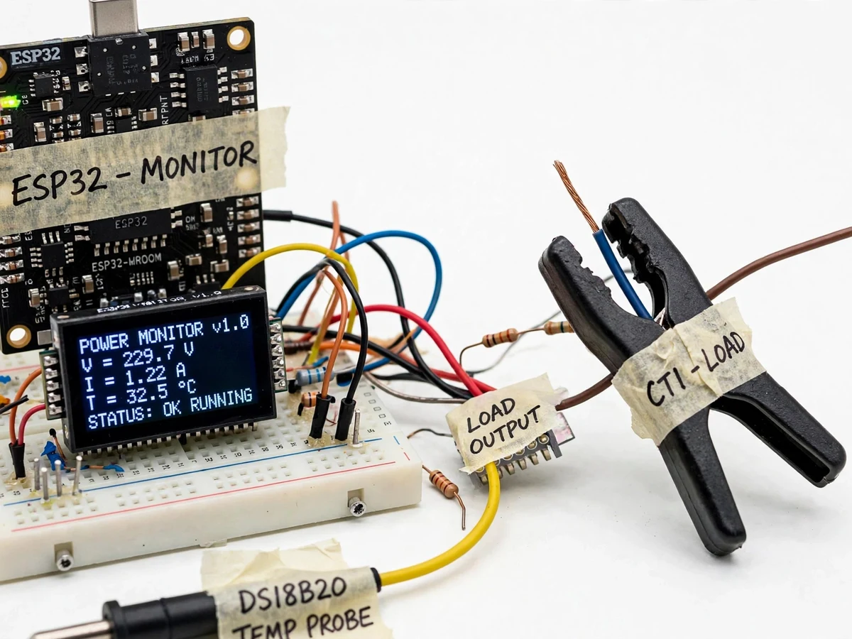
Waterproof DS18B20 probe tracking the transformer oil temperature.
Follow the working sequence
How it works
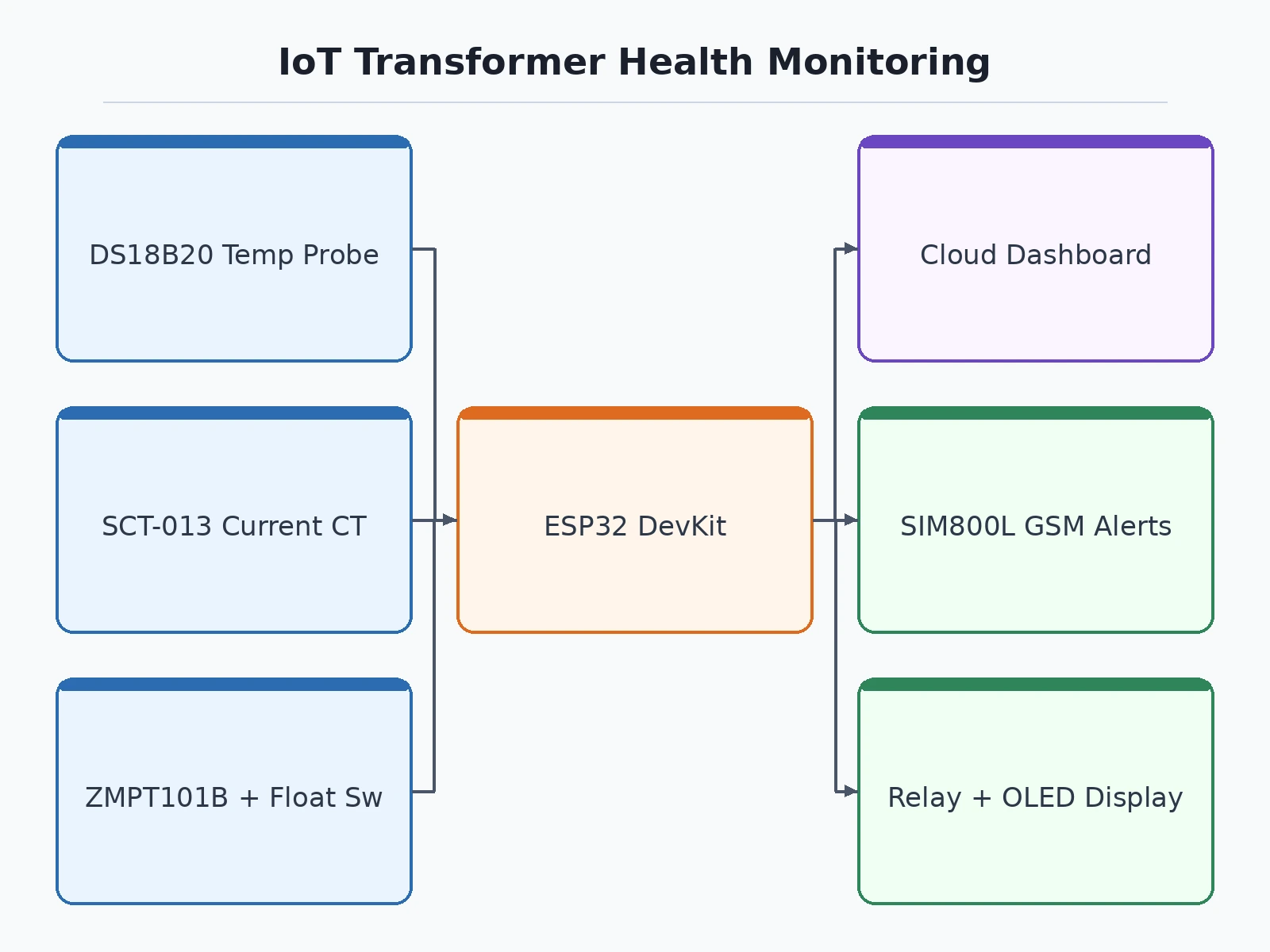
- The sensors continuously sample oil temperature, load current, input/output voltage and oil level.
- The ESP32 processes the readings, computes RMS current and voltage, and compares each parameter against its configured alarm threshold.
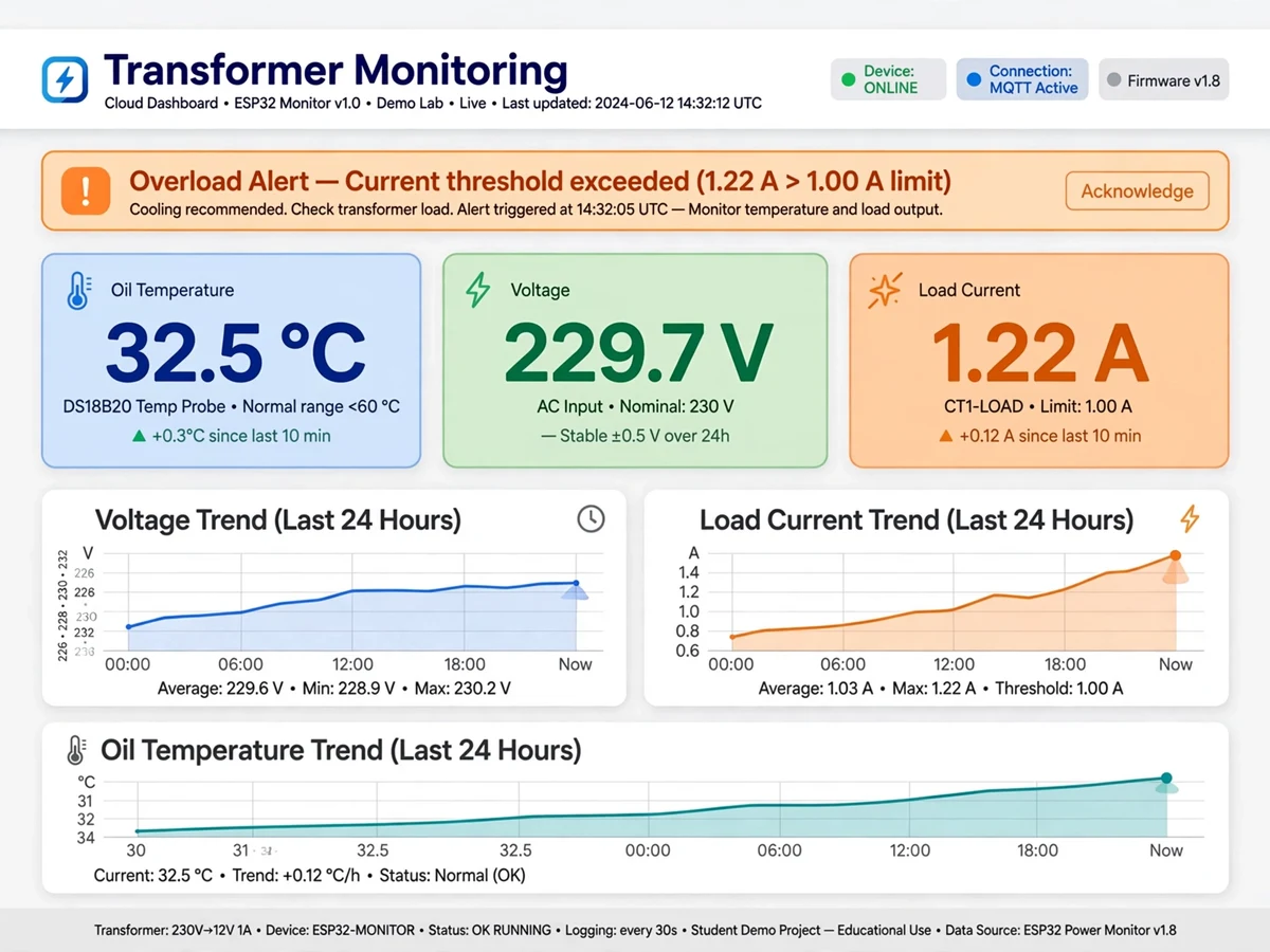
- Live readings appear on the onboard OLED display and are pushed over WiFi (MQTT/HTTP) to the cloud dashboard.
- When a threshold is crossed — oil temperature rising past the set limit, or load current exceeding the rated value — the GSM module fires an SMS alert instantly.
- On a severe fault, the relay output can trip the load automatically. The logged trend data demonstrates predictive maintenance: gradual temperature rise or creeping load imbalance visible days before a failure.
Project features
- Oil temperature monitoring with DS18B20 digital probe (±0.5°C per the sensor datasheet)
- Load current sensing with non-invasive SCT-013 split-core current transformer
- Input and output voltage monitoring with ZMPT101B AC voltage sensor modules
- Oil-level detection with float switch — alerts on low oil before damage occurs
- Live cloud dashboard with trend graphs for every parameter
- SMS alerts via GSM on overload, overheating, low oil or voltage anomalies
- Fully configurable alarm thresholds for temperature, current and voltage
- Relay trip output for automatic load disconnection on severe faults
- On-device OLED display showing live readings during demos
- Data logging for trend analysis and report graphs
What is included
- Assembled transformer-monitoring prototype with demo model
- Complete source code (Arduino IDE, well-commented)
- Circuit diagram and wiring schematic
- Project report PDF (synopsis, design, results, conclusion)
- PPT presentation for final review
- Viva Q&A preparation document
- Cloud dashboard and GSM setup guide
FAQs
- Is it safe to demo a transformer project in college? Yes — the build uses a scaled low-voltage model transformer and load bank, so no high-voltage handling is needed. The sensing and alert logic mirrors real substation practice.
- What temperature and current thresholds should be set? Utility practice typically alarms top-oil temperature around 90°C and trips near 105°C, with overload flagged above the rated current. For the demo model these are scaled down; every threshold is configurable in firmware and the report documents the chosen values with justification.
- How does the SCT-013 current transformer work? It is a split-core CT with a 100 A : 50 mA ratio — it clamps around the load wire without breaking the circuit, and the ESP32 converts the small secondary current into an RMS load-current reading. The report walks through the CT-ratio calculation.
- Does the project predict failures or just display readings? Both. Alerting handles the present; the logged trend data is the predictive part — a slowly rising oil temperature or a growing input-output voltage difference signals developing trouble before a burnout. That predictive-maintenance angle is the strongest review talking point.
- WiFi or GSM — which does it use? Both. WiFi feeds the cloud dashboard for campus demos; GSM sends SMS alerts independently, which mirrors how remote substations report where internet is unreliable.
- Can it disconnect the load on a fault? Yes — a relay trip output is included for severe faults such as extreme over-temperature. It demonstrates the step from monitoring to protection.
Advantages
- Four-parameter monitoring: oil temperature (DS18B20, ±0.5°C per the sensor datasheet), load current (SCT-013 split-core CT), input/output voltage (ZMPT101B) and oil level (float switch).
- Live cloud dashboard with trend graphs for every parameter, plus data logging for report graphs.
- GSM SMS alerts on overload, overheating, low oil or voltage anomalies.
- Relay trip output for automatic load disconnection on severe faults.
- Fully configurable alarm thresholds with an on-device OLED display showing live readings during demos.
Disadvantages
- The supplied demo uses a scaled low-voltage model transformer for safe lab demonstration — not connected to real 11 kV/440 V distribution equipment.
- Hobby-grade sensor accuracy is indicative; it demonstrates the monitoring principle rather than utility-grade metering precision.
- SMS alerts need a GSM SIM with balance and network coverage; cloud features need WiFi.
- Thresholds must be calibrated to the demo transformer's ratings — the report documents the full calibration procedure.
Limitations & prerequisites
- The supplied demo uses a scaled low-voltage model transformer for safe lab demonstration — it is not connected to real 11 kV/440 V distribution equipment.
- Hobby-grade sensor accuracy is indicative; it demonstrates the monitoring principle rather than utility-grade metering precision.
- SMS alerts need a GSM SIM with balance and network coverage; cloud features need WiFi.
- Thresholds must be calibrated to the demo transformer's ratings — the report documents the full calibration procedure.
Components & software requirements
- ESP32 DevKit (WiFi, dual-core 240 MHz)
- SCT-013 split-core current transformer
- 2x ZMPT101B AC voltage sensor modules
- DS18B20 waterproof temperature probe
- Float switch (oil-level detection)
- SIM800L GSM module with antenna
- Relay module (protective trip output)
- 0.96" SSD1306 OLED display
Specifications
| Parameter | Value |
|---|---|
| Microcontroller | ESP32 (240 MHz dual-core, WiFi 802.11 b/g/n) |
| Current sensing | SCT-013 CT, 0–100 A range (demo scaled to model transformer rating) |
| Voltage sensing | ZMPT101B, 0–250 V AC, input & output channels |
| Temperature range | −55°C to +125°C (±0.5°C from −10°C to +85°C) |
| Oil level | Float switch, digital high/low |
| GSM | SIM800L quad-band, SMS on threshold crossing |
| Display | 0.96" OLED, 128×64 |
| Connectivity | WiFi (MQTT/HTTP); GSM for SMS alerts |
| Update interval | 5–10 s (configurable) |
| Alarm thresholds | Fully configurable (temperature, current, voltage, oil level) |
| Trip output | Relay, 10 A / 250 V AC contacts |
Download free synopsis (PDF)
Enter your name and WhatsApp number — the synopsis PDF downloads immediately. We may send occasional project updates on WhatsApp; no spam.
Yadav et al. (2023), Int. J. of Innovative Research in Technology (IJIRT)