
More project photos (2)
The problem
An IoT-based smart shoe with step counting and fall alerts using ESP32 is a wearable prototype that counts the wearer's steps and raises an alert when it detects a fall. An MPU-6050 sensor in the shoe measures acceleration and rotation, an ESP32 reads them fifty times a second, and a phone dashboard shows live steps, distance and fall alerts. Falls are a serious risk for elderly people and anyone walking alone: a person who has fallen may be unable to reach a phone, and every minute without help makes recovery harder. Fitness bands count steps but cannot tell a hard fall from a dropped device, and pendant alarms are often left at home. This project puts the sensing where the motion actually happens — in the shoe — so step counting follows real foot strikes and fall detection follows real impact and orientation change, with a cancel window so a wearer who is fine can stop a false alarm.
3.7 V Li-ion battery with a TP4056 charging module, recharged over USB.
Follow the working sequence
How it works
From sensor to alert, the smart shoe works as one continuous chain: the MPU-6050 measures acceleration and rotation, the ESP32 turns those readings into steps and fall decisions, and Bluetooth Low Energy carries the results to the phone dashboard and, when needed, to an emergency contact. The sensor samples three-axis acceleration and three-axis rotation fifty times a second, and the ESP32 watches the acceleration signal for the sharp peak each heel strike produces, counting one step per peak and estimating distance from a configurable stride length. For falls, the firmware looks for three things in sequence: a sudden acceleration spike, a large change in the shoe's orientation, and then stillness, which together separate a real fall from sitting down quickly or dropping the shoe. When that pattern appears, the shoe buzzes and vibrates locally and starts a thirty-second cancel window; if the wearer does not cancel, the ESP32 sends an alert through the paired phone with the phone's live location.
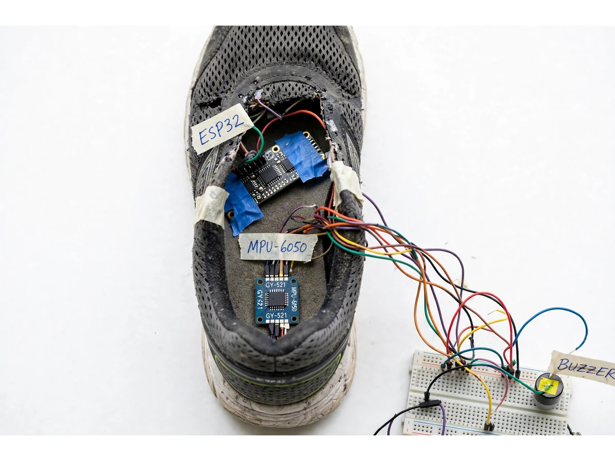
- The MPU-6050 IMU, mounted flat under the heel area of the shoe, samples 3-axis acceleration and 3-axis rotation at 50 Hz and sends the readings to the ESP32 over I2C.
- The ESP32 filters the acceleration signal and detects step peaks: each heel strike produces a sharp peak, and one peak above the threshold counts as one step.
- Distance is estimated from the step count multiplied by a configurable stride length (0.75 m design target), and the dashboard converts steps into an estimated calorie figure.
- In parallel, the firmware watches for the fall pattern: an acceleration spike above the design-target threshold, followed by an orientation change, followed by stillness.
- When the fall pattern appears, the buzzer sounds and the vibration motor runs, and a 30-second cancel window starts on the dashboard and on the shoe.
- If the wearer cancels in time, the event is logged as cancelled and no message is sent. If the window expires, the ESP32 sends the alert over BLE to the paired phone.
- The phone app sends the emergency message to the configured contact with the phone's live GPS location, and the fall event is added to the dashboard's event log with its time.
Tech stack:
- ESP32 (ESP32-WROOM-32) with Arduino IDE firmware
- MPU-6050 6-axis IMU (GY-521 breakout) over I2C
- Bluetooth Low Energy (BLE) link to the phone
- Wi-Fi 802.11 b/g/n for dashboard sync where available
- HTML, CSS and JavaScript companion dashboard
- 3.7 V Li-ion battery with TP4056 charging module
- Vibration motor and buzzer for local alerts
- I2C communication at up to 400 kHz
| Parameter | Value |
|---|---|
| Controller | ESP32-WROOM-32 · dual-core Xtensa LX6 up to 240 MHz (datasheet value) |
| IMU | MPU-6050 · accelerometer ±2 g to ±16 g · gyroscope ±250 °/s to ±2000 °/s (datasheet values) |
| IMU supply | 2.375 V to 3.46 V chip VDD (datasheet value) · 3.3 V to 5 V on GY-521 breakout (datasheet value) |
| IMU interface | I2C up to 400 kHz (datasheet value) · 16-bit ADC per axis (datasheet value) |
| Sampling rate | 50 Hz (design target) |
| Step detection | Accelerometer peak detection · under 20 ms from peak to counted step (design target) |
| Fall trigger | Acceleration spike above 2.5 g + orientation change above 60° + 2 s stillness (design targets) |
| Cancel window | 30 s (configurable) |
| Connectivity | BLE 4.2 + Wi-Fi 802.11 b/g/n 2.4 GHz up to 150 Mbps (datasheet value) |
| BLE range | Approximately 10 m (design target) |
| Battery | 3.7 V Li-ion · approximately 8–10 h typical use (design target) |
| Distance estimate | Stride length 0.75 m (design target · adjustable) |
| Dashboard | Companion web dashboard · live steps · daily history · fall-event log |
Project features
The smart shoe's most useful capabilities are its step counting, its fall detection with a wearer cancel window, its local buzzer and vibration alert, and its companion dashboard that keeps steps, distance and alerts visible on the phone. Step counting runs entirely on the shoe: the ESP32 reads the MPU-6050 accelerometer and counts heel-strike peaks, so steps keep accumulating even when the phone is out of range, and the total syncs over Bluetooth Low Energy when the phone reconnects. Fall detection pairs a sudden-acceleration check with an orientation-change check and a short stillness check, then gives the wearer thirty seconds to cancel before any message leaves the phone, which keeps ordinary stumbles from alarming family members. The dashboard turns the raw counts into daily distance, a weekly history chart and a fall-event log, and the whole prototype runs from a rechargeable lithium battery with a charging module, so it can be worn through a normal day.
- [Step counting by accelerometer peak detection] Each heel strike sends a sharp acceleration peak through the shoe; the ESP32 counts a step only when the peak crosses a threshold and the signal falls back below it, so one strike is one count. Counting runs on the shoe itself, so steps are not lost when the phone is out of range. (Implemented)
- [Fall detection with a 30-second cancel window] A fall is flagged only when three things happen in sequence: a sudden acceleration spike, a large orientation change, and then stillness. The wearer gets 30 seconds to cancel before any alert is sent, which keeps ordinary stumbles from alarming family members. (Implemented)
- [Local buzzer and vibration alert] The moment a possible fall is flagged, a buzzer sounds and a vibration motor buzzes inside the shoe, so the wearer knows an alert is about to go out even if the phone is in another room. (Implemented)
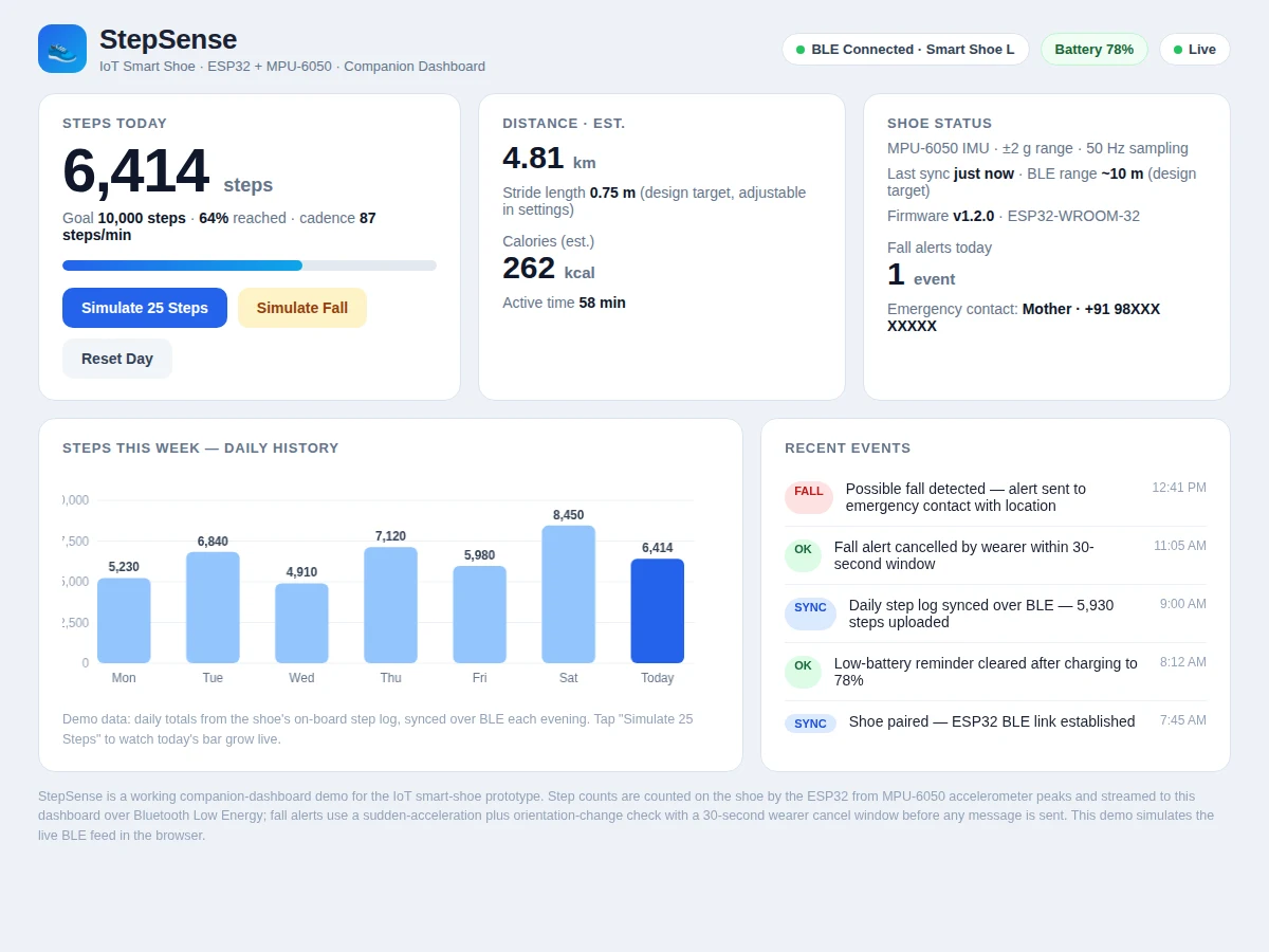
- [Companion phone dashboard] A web dashboard shows live steps, estimated distance, calories, a daily step goal bar and a weekly history chart, plus a log of fall events with times. It connects to the shoe over Bluetooth Low Energy. (Implemented)
- [Emergency alert with phone location] If the cancel window expires without a response, the paired phone sends an alert message to the configured emergency contact with the phone's live location. The shoe itself carries no GPS module; location comes from the phone. (Implemented)
- [Rechargeable battery with charging] A 3.7 V lithium battery powers the shoe and recharges through a TP4056 charging module over USB, so the prototype can be worn through a normal day and charged overnight. (Implemented)
- [Daily history and step-goal tracking] The dashboard keeps a day-by-day step history and a configurable daily step goal, so the wearer can see weekly activity at a glance instead of only a single live number. (Implemented)
Optional on request: an on-shoe GPS module instead of phone-based location, and a heart-rate sensor in the shoe collar. Future scope: gait-pattern analysis and uneven-surface warnings.
What is included
- Working smart-shoe prototype (ESP32 + MPU-6050 + buzzer + vibration motor + battery)
- Complete firmware source code with step-counting and fall-detection logic
- Companion phone dashboard (live steps, distance, history chart, fall-event log)
- Circuit diagram and wiring documentation
- Component list with part details
- Project report PDF (background, working, results, limitations)
- PPT presentation for final review
- Viva Q&A preparation document (IMU working, peak detection, BLE, fall logic)
- Project abstract PDF
Limitations & prerequisites
- This is an academic prototype, not a medical device: it does not diagnose, treat or replace certified medical equipment or professional supervision.
- Fall detection is threshold-based with design-target thresholds; it has not been validated on real falls, so false alarms and missed falls are both possible.
- Step-count accuracy depends on IMU mounting, walking style and calibration; running, shuffling or uneven ground can miscount steps.
- BLE range is approximately 10 m (design target) and drops through walls; step data syncs only when the phone is back in range.
- The location in an alert comes from the paired phone's GPS, not from the shoe, so an alert needs the phone nearby and switched on.
- Battery runtime of approximately 8–10 h is a design target and varies with BLE advertising interval, alert frequency and battery age.
- The prototype shoe is a demonstration build: the electronics are taped and wired by hand and are not waterproof, washable or suitable for daily wear without re-housing.
Frequently Asked Questions
How does the shoe count steps?
The MPU-6050 accelerometer inside the shoe records acceleration fifty times a second, and each heel strike produces a sharp peak in that signal. The ESP32 counts one step for every peak that crosses the threshold and then falls back below it. Counting runs on the shoe itself, so steps keep accumulating when the phone is out of range and sync over BLE when it reconnects. Distance is estimated from steps multiplied by a configurable stride length.
How does fall detection work, and what happens if the wearer is fine?
A fall is flagged only when three things happen in sequence: a sudden acceleration spike, a large change in the shoe's orientation, and then stillness. The shoe immediately buzzes and vibrates and a 30-second cancel window starts, so a wearer who is fine can stop the alert before anyone is contacted. Only if the window expires does the phone send the emergency message with its live location.
Does the shoe need internet or Wi-Fi to work?
No. Step counting, fall detection and the local buzzer and vibration alert all run on the shoe itself with no connectivity at all. Bluetooth Low Energy carries steps and alerts to the phone dashboard, and Wi-Fi is used only where the dashboard syncs online. The emergency message needs the paired phone to have mobile signal; the shoe alone cannot send an SMS.
Is this project suitable for a final-year project?
Yes — for Electronics, E&TC, IoT and Biomedical-related programmes. It demonstrates embedded sensing with a real IMU, signal processing on a microcontroller, threshold-based event detection, BLE communication and a working companion dashboard, which together give the team concrete hardware, firmware and software to explain in the viva.
Can the project be customised?
Yes. Common changes are a different cancel-window length, an on-shoe GPS module instead of phone-based location, a heart-rate sensor in the shoe collar, a different daily step goal, an additional dashboard view for a caregiver, and a second alert contact for shared care. The IMU mounting is the one part that should not be moved casually: in the bench build, a tilted or loose mount produced false step peaks on every foot lift, so the module is taped flat under the heel and calibrated once at power-on.
Components & software requirements
- ESP32 (ESP32-WROOM-32) with Arduino IDE firmware
- MPU-6050 6-axis IMU (GY-521 breakout) over I2C
- Bluetooth Low Energy (BLE) link to the phone
- Wi-Fi 802.11 b/g/n for dashboard sync where available
- HTML, CSS and JavaScript companion dashboard
- 3.7 V Li-ion battery with TP4056 charging module
- Vibration motor and buzzer for local alerts
- I2C communication at up to 400 kHz
Delivery information
Built-to-order project. Delivery timeline is shared after order confirmation based on current queue.
Support terms
Complete documentation, setup guide, and viva preparation included. Support for setup and explanation provided.
Download free synopsis (PDF)
Enter your name and WhatsApp number — the synopsis PDF downloads immediately. We may send occasional project updates on WhatsApp; no spam.