
More project photos (2)
The problem
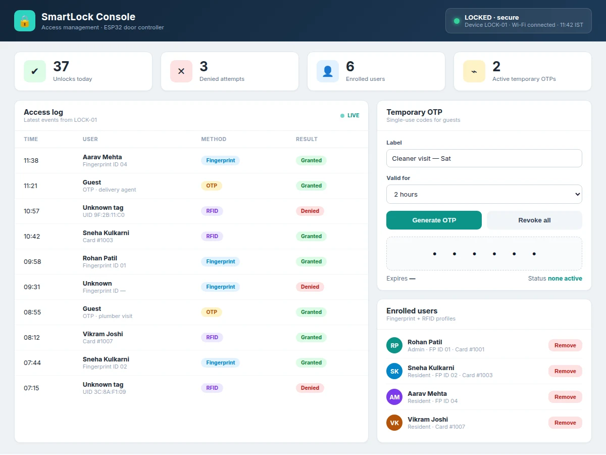
House keys get lost, copied and shared; biometric and RFID readers fix that, but a single credential becomes a single point of failure — one dead sensor or one forgotten card and nobody gets in. This project solves the problem with a multi-credential IoT door lock: an ESP32 controller accepts fingerprints through an R307 optical module, RFID cards and tags through an RC522 reader, and short-lived OTP codes entered on a 4×4 membrane keypad for visitors who cannot be enrolled permanently. All three paths converge on a relay-driven 12 V solenoid bolt, and every event — granted, denied, OTP issued, OTP expired — is published over Wi-Fi as MQTT messages to a companion access-management dashboard showing the live log, enrolled users and active guest codes.
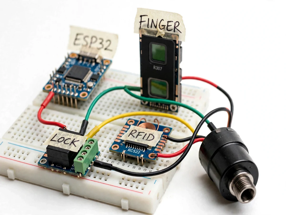
The hardware is deliberately built like a real student prototype on a breadboard: visible modules, labeled wiring, and an enrollment routine that stores fingerprints inside the sensor module's own flash and card UIDs in the ESP32's EEPROM. The software side is two working pieces: Arduino firmware on the ESP32 handling all three credential paths with a clear priority and fallback order, and a single-file HTML/CSS/JS dashboard that subscribes to the MQTT topics and renders the access log, OTP issuance panel and user list in real time. Because the whole stack is built in the open with standard parts, the student can genuinely explain the wiring, the protocol flow and the security trade-offs in the viva.
Resident or guest presenting a credential at the door.
Follow the working sequence
How it works
- The ESP32 boots, connects to Wi-Fi, subscribes to the
smartlock/lock01/commandsMQTT topic, and initializes the R307 fingerprint module (UART, 57600 baud), the RC522 RFID reader (SPI) and the 4×4 keypad scan loop. - On each scan cycle the firmware polls the fingerprint sensor first, then the RFID field, then the keypad buffer — the first credential presented is evaluated; presentation order defines priority, no combination is required.
- A fingerprint match is confirmed by the R307 module itself against its on-board templates (match typically under 1 second); an RFID card is authorized by comparing its UID against the enrolled list in EEPROM.
- An OTP is accepted only if it matches a dashboard-issued code whose validity window has not expired; expired or unknown codes are rejected and logged as denied attempts.
- On acceptance, the firmware energizes the relay for the configured unlock window (default 7 seconds), drives the solenoid bolt open, publishes a
grantedevent with user, method and timestamp, then releases and relocks. - On rejection, a
deniedevent is published with the reason (unknown tag, unknown fingerprint, bad OTP, lockout); five consecutive denials trigger the 60-second keypad lockout. - The dashboard subscribes to the event topics and updates the access log, statistics counters, OTP panel and user list in real time; OTP issuance publishes back on the command topic, which the ESP32 caches in RAM.
Tech stack:
- ESP32 · Arduino IDE (C++ firmware)
- R307 fingerprint sensor module · RC522 RFID reader
- MQTT · Wi-Fi telemetry
- 12 V solenoid lock · relay driver
- 4×4 membrane keypad
- HTML · CSS · JavaScript dashboard (single file)
- Git
| Parameter | Value |
|---|---|
| Controller | ESP32 dev module (Wi-Fi, dual-core 240 MHz) |
| Fingerprint sensor | R307 optical module, UART 57600 baud |
| Fingerprint template capacity | Up to 1,000 templates (module datasheet value) |
| Fingerprint match time | Typically < 1 s (module datasheet value) |
| FAR / FRR | < 0.001% / < 1% (module datasheet values, not measured claims) |
| RFID reader | RC522, 13.56 MHz, SPI interface |
| RFID read range | Approximately 3–5 cm (expected, tag-dependent) |
| Keypad | 4×4 membrane matrix, GPIO scan |
| Lock actuator | 12 V DC solenoid bolt, relay-driven |
| Unlock window | 5–10 s, configurable (default 7 s) |
| OTP format | 6 digits, single-use, 30 min–12 h validity (configurable) |
| Lockout | 60 s keypad lockout after 5 consecutive denials |
| Telemetry | MQTT over Wi-Fi (topics: events, commands, status) |
| Power | 12 V DC adapter (lock) with 5 V / 3.3 V rails for logic |
Project features
- [Triple-credential access] Unlock with any of three independent methods — enrolled fingerprint on the R307 module, authorized RFID card/tag on the RC522 reader, or a temporary OTP keyed in on the 4×4 membrane keypad. If one reader fails, the other two still work.
- [Temporary OTP guest codes] The dashboard issues 6-digit single-use OTPs with configurable expiry (30 minutes to 12 hours); the ESP32 validates the code and the time window locally, so a guest never needs a card or fingerprint enrollment.
- [Live access log over MQTT] Every event — granted, denied, unknown tag, OTP issued, OTP expired — is published to structured MQTT topics and rendered live on the dashboard with user, method, timestamp and result.
- [Enrolled-user management] Fingerprints enroll into the R307 module's on-board template storage (up to 1,000 templates) via a guided admin routine; RFID card UIDs register to the ESP32 EEPROM with names, and both lists surface on the dashboard.
- [Denied-attempt handling] After five consecutive failed attempts the keypad locks out for 60 seconds and the denial burst is flagged on the dashboard — a simple, honest brute-force deterrent.
- [Auto-relock and fail-safe wiring] The solenoid bolt releases for a configurable 5–10 seconds then relocks automatically; the lock defaults to the locked state on power loss, and a 12 V supply with a 5 V logic rail keeps the relay switching clean.
- [Dashboard simulation hooks] The single-file dashboard ships with working controls — generate/revoke OTPs, add access events, manage users — so the demo runs end-to-end even before the hardware is in hand.
What is included
- Complete wired prototype: ESP32, R307 fingerprint module, RC522 reader, 4×4 keypad, relay module, 12 V solenoid lock, breadboard and labeled wiring
- Full Arduino firmware: triple-credential state machine, enrollment routine, OTP validation, MQTT client, lockout logic
- Single-file access-management dashboard (HTML/CSS/JS): live access log, OTP issuance panel, enrolled-user list, statistics
- Wiring diagram and connection table (module → GPIO pin mapping)
- Enrollment and calibration guide (fingerprint enrollment steps, RFID registration, OTP workflow)
- Project report PDF (background, system design, circuit explanation, protocol flow, limitations, future scope)
- PPT presentation for final review
- Viva Q&A preparation document (fingerprint matching, RFID security, MQTT, OTP design, failure modes)
Limitations & prerequisites
- The R307's FAR/FRR figures are the module's datasheet values — this build does not include a measured biometric accuracy test, and no such claim is made.
- RFID cards (Mifare Classic) transmit their UID in the clear; UIDs can be cloned with cheap tools, so the RFID path is a convenience layer, not high security — documented honestly in the report.
- OTP validation needs Wi-Fi: if the ESP32 is offline, the dashboard cannot push new OTPs (previously issued, unexpired OTPs cached in RAM still work until reboot).
- The solenoid draws significant current when energized — it needs a genuine 12 V / 2 A supply; underrated adapters cause brownouts that reset the ESP32.
- Fingerprint recognition degrades with wet, dirty or injured fingers; enrollment quality during setup directly determines day-to-day reliability.
- This is a working prototype on a breadboard, not a certified door lock — it is not tested against forced entry, and the report states this plainly.
- The dashboard is a single-file local demo that talks to an MQTT broker — it is not a hosted multi-tenant cloud service with accounts and billing.
Frequently Asked Questions
How do the three access methods work together?
The firmware polls fingerprint, RFID and keypad in a fixed priority order each scan cycle and acts on whichever credential is presented first. They are independent fallbacks, not multi-factor — any one valid credential opens the lock, so a dead sensor never strands you.
How do temporary OTPs work for guests?
From the dashboard you generate a 6-digit code with a validity window (30 minutes to 12 hours) and a label like "plumber visit". The code is pushed to the ESP32 over MQTT; the guest types it on the keypad. It is single-use, expires automatically, and every OTP event lands in the access log.
What happens if the Wi-Fi goes down?
The lock keeps working locally — fingerprint and RFID validation happen entirely on the device, and cached unexpired OTPs remain valid. Only new OTP issuance from the dashboard pauses until Wi-Fi returns.
How secure is the RFID path really?
Honestly, modestly: 13.56 MHz Mifare Classic cards broadcast their UID in plaintext and can be cloned. The report documents this as a known limitation. For real deployments the fingerprint or OTP path is the stronger credential; RFID is kept as the fast convenience method.
Can fingerprints be enrolled and deleted?
Yes. An admin routine on the ESP32 walks through enrollment (place finger twice for a good template), stores the template in the R307's own flash — up to 1,000 of them — and the dashboard's user list supports removing users, which clears the template and the EEPROM card entry.
Is this project suitable for a final-year project?
Yes — for Electronics, IoT & Embedded Systems and Electrical programs. It combines sensor interfacing, embedded state machines, wireless telemetry (MQTT) and a working web dashboard, with honest documented limits that make strong viva material. Suitable for B.E./B.Tech final-year projects in Electronics, IoT & Embedded Systems and Electrical.
Components & software requirements
- ESP32 · Arduino IDE (C++ firmware)
- R307 fingerprint sensor module · RC522 RFID reader
- MQTT · Wi-Fi telemetry
- 12 V solenoid lock · relay driver
- 4×4 membrane keypad
- HTML · CSS · JavaScript dashboard (single file)
- Git
Delivery information
Built-to-order project. Delivery timeline is shared after order confirmation based on current queue.
Support terms
Complete documentation, setup guide, and viva preparation included. Support for setup and explanation provided.
Download free synopsis (PDF)
Enter your name and email — the synopsis PDF downloads immediately. We may send occasional project updates; no spam, unsubscribe anytime.