
More project photos (2)

The problem
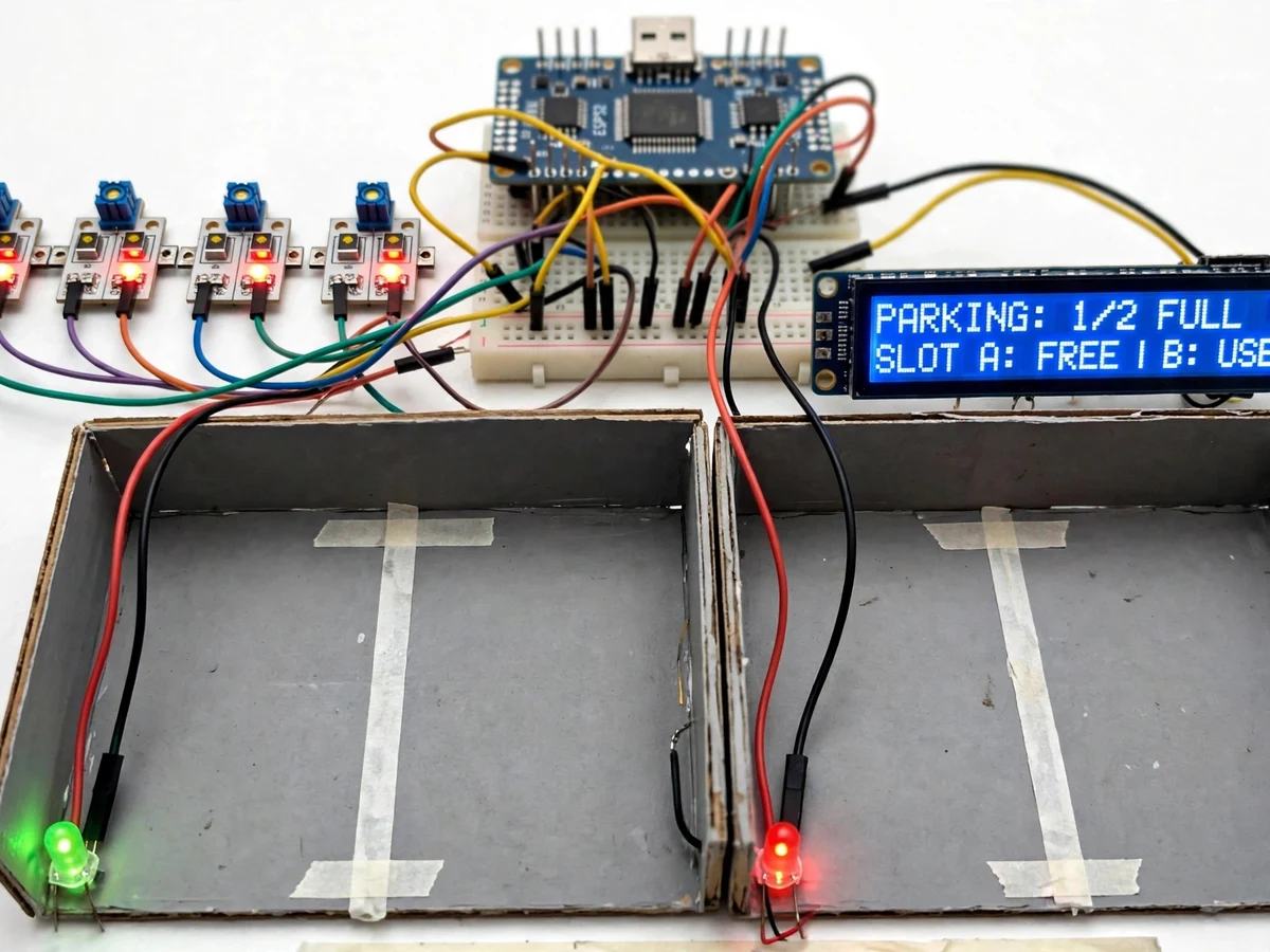
Drivers circle parking lots hunting for a free bay while half the bays sit empty one floor up — the information exists at the sensor but never reaches the driver. The fix is a per-slot sensing layer with a display at the entrance. This project builds that layer as a student prototype: each parking bay gets an IR obstacle sensor, an ESP32 polls all slots, and the status is shown on red/green LEDs per bay, a 16x2 LCD summary at the "entrance", and a cloud dashboard with a live slot map. The firmware debounces sensor readings so a person walking past a bay does not flip its state, and only stable changes are published. The dashboard keeps a simple occupancy history, which turns the demo into a small data story about peak hours.
How it works
- Each IR sensor watches its bay; the ESP32 scans all sensor pins in a loop every few hundred milliseconds.
- Raw readings pass through the debounce filter — a slot flips state only after N consecutive consistent samples (default 5).
- On a confirmed change, the ESP32 updates the slot's LED (green for free, red for occupied) and refreshes the LCD summary.
- The new state is published over Wi-Fi to the cloud dashboard, which repaints the live slot map within seconds.
- Every change is timestamped in the dashboard log, building the occupancy history used for the peak-hours view.
- The LCD always shows the current totals, so the entrance display works even if Wi-Fi drops — only the cloud map needs connectivity.
Tech stack:
- ESP32 development board (Wi-Fi)
- Arduino IDE (C/C++ firmware)
- IR obstacle-avoidance sensor modules (one per slot)
- Red/green LED pairs with resistors
- 16x2 LCD with I2C backpack
- Cloud dashboard (ThingSpeak/Blynk class) over MQTT/HTTP
- Miniature parking-bay model with demo vehicle
- 5 V DC supply
| Parameter | Value |
|---|---|
| Controller | ESP32, 3.3 V logic, Wi-Fi 802.11 b/g/n |
| Slots (demo) | 4 bays, expandable in firmware |
| Sensor | IR obstacle module, adjustable range approximately 2–30 cm |
| Debounce | 5 consecutive consistent samples (configurable) |
| Scan rate | Approximately 5 Hz per full slot scan |
| Display | 16x2 LCD (I2C) + red/green LED per slot |
| Dashboard | Live slot map + timestamped occupancy log, MQTT/HTTP |
| Power | 5 V DC supply |
Project features
- [Per-slot IR sensing] Each parking bay has an IR obstacle-avoidance sensor; the ESP32 polls all slots in a scan loop with per-sensor sensitivity adjustment.
- [Debounced state logic] A slot changes state only after consecutive consistent readings, so pedestrians or passing shadows do not cause flickering status.
- [LED per bay] Red/green LED pairs at each slot give instant at-a-glance status, wired through current-limiting resistors.
- [Entrance LCD summary] A 16x2 LCD shows total free slots and per-slot status (e.g. "FREE: 2/4, A:OCC B:FREE") for the driver at the gate.
- [Live cloud slot map] Slot states are published over Wi-Fi (MQTT/HTTP) to a dashboard showing a live map of the lot with free/occupied coloring.
- [Occupancy history] The dashboard logs state changes with timestamps, producing a simple peak-hours view of lot usage.
- [Scalable slot count] The firmware's slot table is configurable — the demo ships with four bays and the code supports expansion by adding sensor channels.
What is included
- Working prototype: ESP32, 4 IR sensors, LEDs, LCD, miniature parking bays with demo car
- Complete ESP32 firmware (slot scanning, debounce logic, LED/LCD drivers, cloud publishing)
- Cloud dashboard setup guide (slot map configuration, history charts)
- Wiring diagram and connection table
- Sensor sensitivity adjustment guide
- Project report PDF (background, sensing and debounce design, methodology, working, results)
- PPT presentation for final review
- Viva Q&A preparation document (IR sensing, debouncing, ESP32 GPIO expansion, MQTT telemetry)
Limitations & prerequisites
- IR sensors detect presence within approximately 2–30 cm; the demo bays are sized to this range — a real lot needs longer-range or different sensing (listed as future scope).
- Direct strong sunlight can saturate IR receivers; the demo is designed for indoor/shaded demonstration.
- Debouncing adds a short delay (about a second) before a state change registers — a deliberate trade-off against flicker, documented in the report.
- The dashboard needs Wi-Fi; the LEDs and LCD keep working locally without it.
- Occupancy history is only as granular as the dashboard's logging interval; it shows trends, not second-by-second analytics.
Frequently Asked Questions
How does it know a slot is occupied?
An IR obstacle sensor watches each bay. When a vehicle (the demo car) enters the sensor's range, the reflected IR trips the sensor; the ESP32 confirms it with debounced readings before marking the slot occupied.
Won't people walking past trigger false readings?
That is what the debounce filter is for — a slot changes state only after several consecutive consistent readings, so a passing pedestrian does not flip it.
What shows the driver the status?
Three layers: red/green LEDs at each bay, a 16x2 LCD summary at the entrance, and a live slot map on the cloud dashboard.
Can it handle more than 4 slots?
Yes — the slot table in firmware is configurable; adding bays means wiring more IR sensors to free GPIO pins (or an expander) and updating the slot count constant.
Would this work in a real parking lot?
The concept scales, but real lots need longer-range sensing (ultrasonic or magnetic per bay) and weatherproofing — both listed as future scope. The prototype proves the sensing, logic and display pipeline.
Is this project suitable for a final-year project?
Yes — for IoT & Embedded programs. It combines multi-sensor interfacing, debounce/state-machine logic, local displays and cloud telemetry in one demonstrable system. Suitable for B.E./B.Tech final-year projects in IoT & Embedded.
Components & software requirements
- ESP32 development board (Wi-Fi)
- Arduino IDE (C/C++ firmware)
- IR obstacle-avoidance sensor modules (one per slot)
- Red/green LED pairs with resistors
- 16x2 LCD with I2C backpack
- Cloud dashboard (ThingSpeak/Blynk class) over MQTT/HTTP
- Miniature parking-bay model with demo vehicle
- 5 V DC supply
Delivery information
Built-to-order project. Delivery timeline is shared after order confirmation based on current queue.
Support terms
Complete documentation, setup guide, and viva preparation included. Support for setup and explanation provided.