
More project photos (2)
The problem
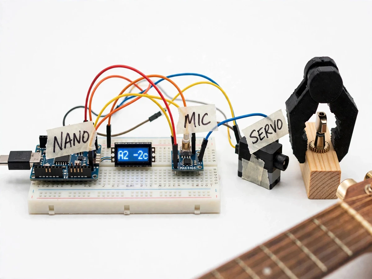
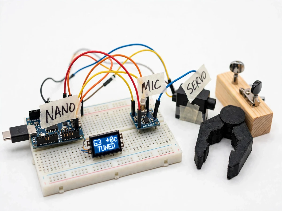
Tuning a guitar by ear is a skill most beginners don't have, and ordinary clip-on tuners still leave the player to turn the peg — slow, fiddly, and hard on strings when done wrong. Digital tuners read pitch well but never close the loop mechanically: they display that a string is flat and leave the correction to your fingers. This project closes that loop. A MAX4466 electret microphone module captures the plucked string; an Arduino Nano samples the signal and runs a 256-point FFT (arduinoFFT library) to find the dominant frequency; firmware maps it to the nearest note of standard tuning and computes cents deviation; a 0.96-inch OLED shows the note name and the sharp/flat reading. When the string is outside the tolerance band, an SG90 servo fitted with a 3D-printed peg winder turns the tuning peg, waits for the string to settle, and re-measures until the reading lands within ±5 cents (design target). The result is a hands-free tuner that demonstrates real-time DSP, sensor conditioning and closed-loop control on a microcontroller budget.
Plucks the string so the microphone captures a clean note for each measurement pass.
Follow the working sequence
How it works
- The MAX4466 electret microphone module captures the plucked string; its adjustable gain is set so the loudest pluck stays within the Arduino Nano's 0–5 V ADC range without clipping.
- Firmware samples the ADC at approximately 9.6 kHz into a 256-sample buffer, applies a Hamming window, and runs the arduinoFFT forward transform to get the magnitude spectrum.
- The dominant spectral peak is found and refined with parabolic interpolation across neighboring bins, pushing resolution finer than the ~37.5 Hz bin spacing toward sub-Hz accuracy (design target).
- The refined frequency is matched to the nearest of the six standard open-string targets (E2 82.41, A2 110.00, D3 146.83, G3 196.00, B3 246.94, E4 329.63 Hz); cents deviation is computed and shown on the OLED with a sharp/flat arrow.
- If the deviation is within ±5 cents (design target), the display shows TUNED and the loop rests; otherwise the firmware computes the correction direction and magnitude.
- The SG90 servo rotates the 3D-printed peg winder — clockwise to sharpen, counter-clockwise to flatten — then pauses approximately one second for the string pitch to settle.
- The system re-samples and repeats steps 2–6 in a closed loop until the reading lands inside the tolerance band, with a servo-travel guard that stops the run before a peg can be forced.
Tech stack:
- Arduino Nano (ATmega328P, 16 MHz)
- MAX4466 electret microphone module
- arduinoFFT library with Hamming window
- SG90 micro servo motor
- 0.96-inch OLED display (SSD1306)
- 3D-printed peg winder attachment
- Arduino IDE (C/C++ firmware)
- Breadboard and jumper wiring
| Parameter | Value |
|---|---|
| FFT size | 256 points, arduinoFFT library (design) |
| Sampling rate | Approximately 9.6 kHz on ATmega328P ADC (design) |
| FFT bin spacing | Approximately 37.5 Hz at 256 points / 9.6 kHz; parabolic interpolation toward sub-Hz (design target) |
| Note targets | E2 82.41, A2 110.00, D3 146.83, G3 196.00, B3 246.94, E4 329.63 Hz (standard tuning, defined values) |
| Tuning tolerance | Within ±5 cents (design target, closed-loop) |
| Servo | SG90, approximately 1.8 kg·cm at 4.8 V (datasheet value) |
| Display | 0.96-inch OLED, SSD1306 — note name, cents, sharp/flat arrow, TUNED state |
| Microphone | MAX4466 electret module with adjustable gain |
| Correction loop | Sample → interpolate → correct → settle ~1 s → re-check (expected) |
| Power | 5 V USB or 5 V battery pack (design) |
Project features
- [FFT pitch detection] The Nano samples the microphone at approximately 9.6 kHz and runs a 256-point FFT with a Hamming window; parabolic interpolation between bins refines the peak toward sub-Hz accuracy (design target), making low E2=82.41 Hz detectable despite the coarse ~37.5 Hz bin spacing.
- [Chromatic note mapping] The detected frequency is compared against the six standard open-string targets (E2, A2, D3, G3, B3, E4); firmware picks the nearest note and computes cents deviation as 1200·log2(f/f_target).
- [Live cents display] The 0.96-inch OLED shows the note name, the cents reading (e.g. E2 +3c) and a sharp/flat direction arrow, updating after every measurement pass.
- [Closed-loop servo correction] When the reading is outside the ±5-cent band (design target), the SG90 servo turns the peg winder in the needed direction, pauses for string settling, and re-measures until the string lands inside tolerance, then shows TUNED.
- [3D-printed peg winder] A custom gripper attachment on the servo horn physically engages the tuning peg button, so the correction is genuinely mechanical rather than just an on-screen suggestion.
- [Target-string selection] A push-button steps through the six strings (or an auto mode), so the firmware knows which target frequency to aim for; an over-rotation guard caps servo travel to protect the peg.
- [FFT spectrum over serial] The raw spectrum can be streamed over USB to the Arduino serial plotter, giving a visible waveform-to-spectrum path for the report and the viva.
- [Quiet-room tuning workflow] A documented procedure: pluck, read, correct, re-check — repeatable by the student and measurable against a reference tuner app for the report's comparison table.
What is included
- Working prototype: Arduino Nano, MAX4466 mic module, OLED, SG90 servo with 3D-printed peg winder, wiring on breadboard
- Complete Arduino firmware: sampling, FFT, note mapping, cents math, servo control loop, OLED UI
- Wiring diagram and component connection list
- 3D-printed peg winder design file (STL) with fitting notes
- Quiet-room tuning procedure plus a reference-tuner comparison table for the report
- Project report PDF (DSP background, FFT method, methodology, results)
- PPT presentation for final review
- Viva Q&A preparation document (FFT, sampling, cents math, closed-loop control)
Limitations & prerequisites
- 256-point FFT gives ~37.5 Hz bins — coarse at E2 (82.41 Hz); sub-Hz accuracy is a design target via interpolation, not a lab-measured claim.
- Noisy rooms degrade pitch detection; the documented workflow assumes a quiet room, not a stage or classroom full of people.
- The SG90 delivers approximately 1.8 kg·cm (datasheet); stiff or seized pegs may not turn — the servo-travel guard prevents forcing a peg to damage.
- A 16 MHz Nano running FFT plus ADC plus servo is a stretch; each correction pass takes roughly 200–300 ms (expected), so tuning one string takes several seconds.
- Ships configured for standard tuning open strings; alternate tunings need the target table edited in firmware.
- ±5 cents is a design target for the closed loop, stated honestly — the report documents whatever tolerance the buyer's own build actually achieves.
Frequently Asked Questions
How does the FFT pitch detection work on a small Arduino?
The Nano samples the electret mic at about 9.6 kHz, fills a 256-sample buffer, applies a Hamming window and runs the arduinoFFT transform. The tallest spectral peak is the plucked string's fundamental; parabolic interpolation between bins refines it finer than the ~37.5 Hz bin spacing, toward sub-Hz accuracy as a design target.
Why is ±5 cents a design target, not a measured result?
Because accuracy depends on the student's own build: mic gain setting, room noise, string quality and servo backlash all move the number. The firmware aims for ±5 cents and reports its own reading; the report compares that reading against a phone reference tuner so the achieved figure is honest.
Can a small SG90 servo really turn a guitar tuning peg?
On a normal, free-moving peg, yes — the 3D-printed winder grips the peg button and the ~1.8 kg·cm (datasheet) servo has enough torque. Seized or corroded pegs can stall it, which is why the firmware has a servo-travel guard that stops before anything is forced.
Will it work in a noisy room?
Not reliably — the mic picks up whatever is loudest, so background music or chatter corrupts the spectrum. The project is documented and demonstrated for a quiet room; making it stage-robust would need a pickup or contact sensor, which is listed as future scope.
Is this project suitable for a final-year project?
Yes — for Electronics, E&TC and Instrumentation programs. It combines analog sensing, real-time DSP on a microcontroller, mechanical actuation and closed-loop control, with honest, measurable results a student can defend.
Components & software requirements
- Arduino Nano (ATmega328P, 16 MHz)
- MAX4466 electret microphone module
- arduinoFFT library with Hamming window
- SG90 micro servo motor
- 0.96-inch OLED display (SSD1306)
- 3D-printed peg winder attachment
- Arduino IDE (C/C++ firmware)
- Breadboard and jumper wiring
Delivery information
Built-to-order project. Delivery timeline is shared after order confirmation based on current queue.
Support terms
Complete documentation, setup guide, and viva preparation included. Support for setup and explanation provided.
Download free synopsis (PDF)
Enter your name and email — the synopsis PDF downloads immediately. We may send occasional project updates; no spam, unsubscribe anytime.