
More project photos (3)
Frequently Asked Questions
Which sensors does it use and why?
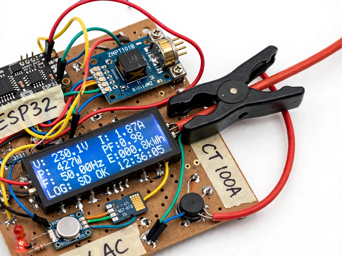
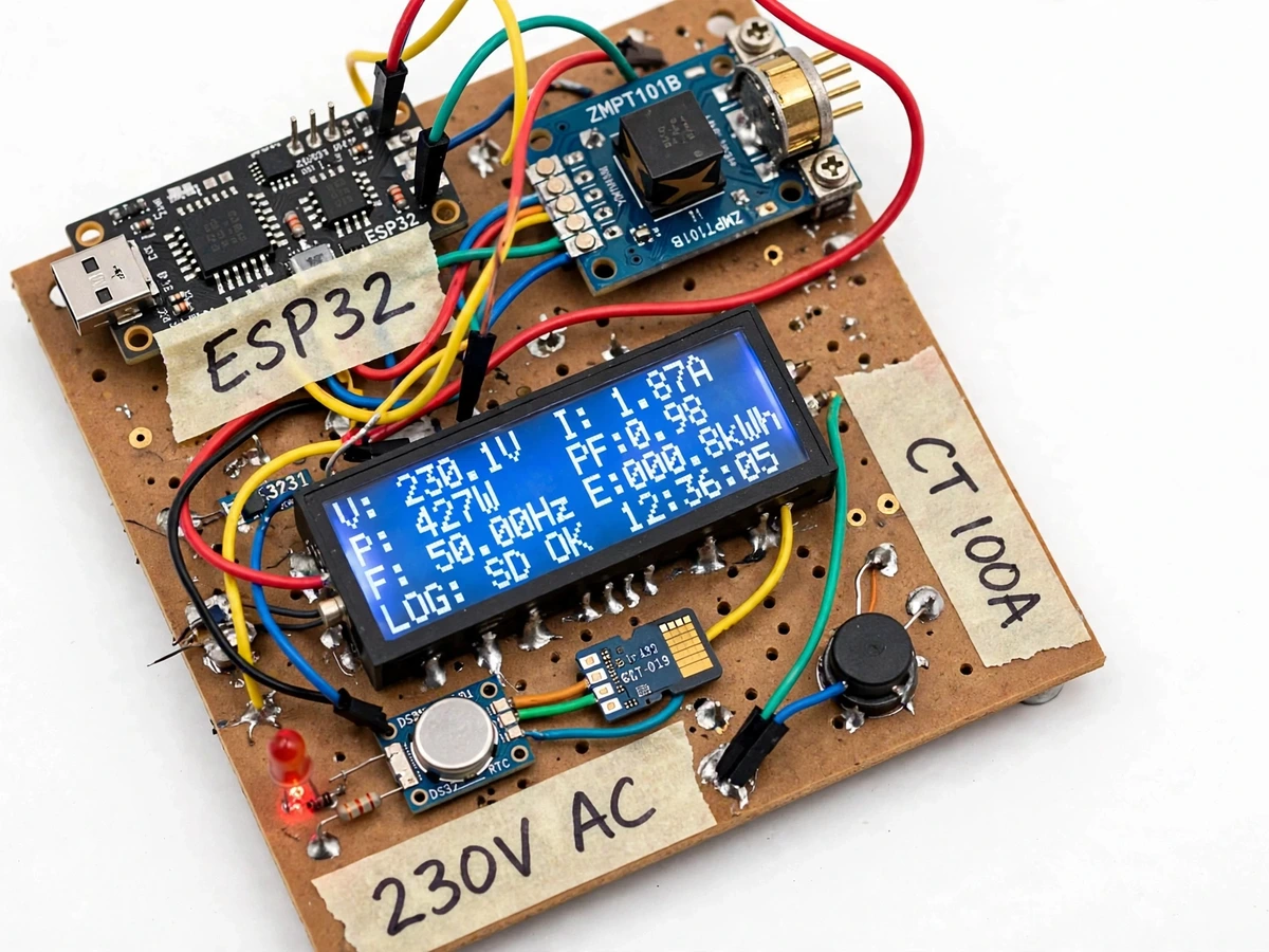
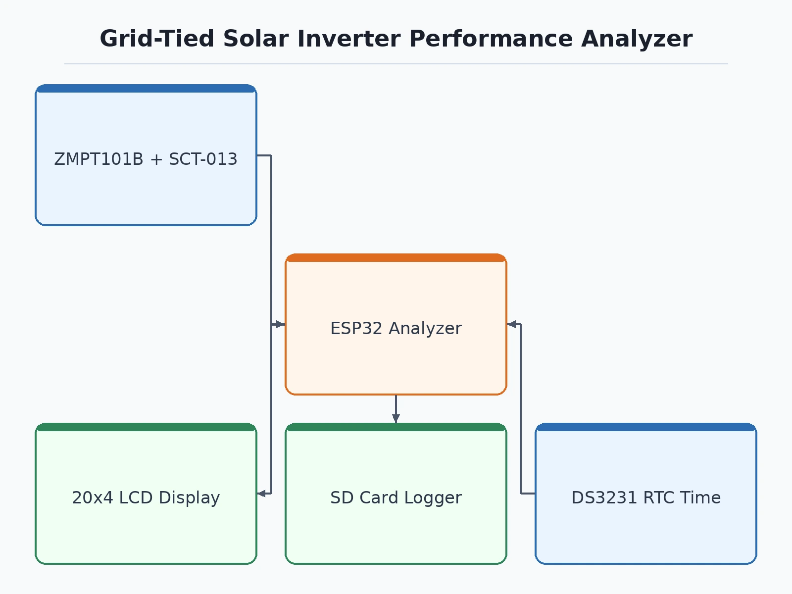
The ZMPT101B for voltage (transformer-isolated, rated 0–250 V AC) and the SCT-013-000 clamp CT for current (100 A : 50 mA, no wire cutting). Both are the standard student-accessible parts for mains measurement, and both calibrate against an ordinary multimeter — which is exactly what the report's calibration section demonstrates.
How is power factor actually computed?
Not estimated: the ESP32 samples voltage and current simultaneously at a ~2,000 samples/s design target, averages the instantaneous v×i products over complete 50 Hz cycles for real power, multiplies Vrms×Irms for apparent power, and divides. The LCD shows the resulting PF live — typically near unity for a healthy grid-tied inverter.
Does it need WiFi or internet?
No. The base build is fully offline: an LCD display plus SD-card logging with RTC timestamps. WiFi upload to a cloud dashboard is an optional customization built on the ESP32's radio — the core analyzer works in a lab or on a rooftop with no connectivity at all.
Is it safe to connect to household mains?
The clamp CT is completely non-invasive, but the voltage sensor taps 230 V AC, so assembly and installation must be done under supervision with the fused sense tap and an insulated enclosure. The build is an academic prototype, not certified metering equipment — stated plainly in the report.
How does the underperformance flag work?
The buyer enters the installed panel capacity (kWp) and an expected performance ratio; each day the firmware compares measured kWh against the expected yield and sounds the buzzer plus red LED when the shortfall passes the set tolerance. It is a screening alert — without an irradiance sensor it cannot say why generation fell, only that it did.
Is this project suitable for a final-year project?
Yes — for Electrical Engineering programs. It demonstrates AC measurement with real sensors, RMS and power-factor computation in firmware, energy integration, data logging and calibration methodology — the instrumentation skill set behind solar O&M, all defensible in a viva. Suitable for B.E./B.Tech final-year projects in Electrical Engineering.
Download free synopsis (PDF)
Enter your name and WhatsApp number — the synopsis PDF downloads immediately. We may send occasional project updates on WhatsApp; no spam.