
More project photos (3)

The problem
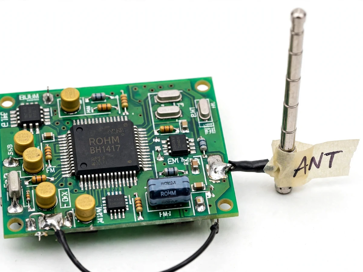
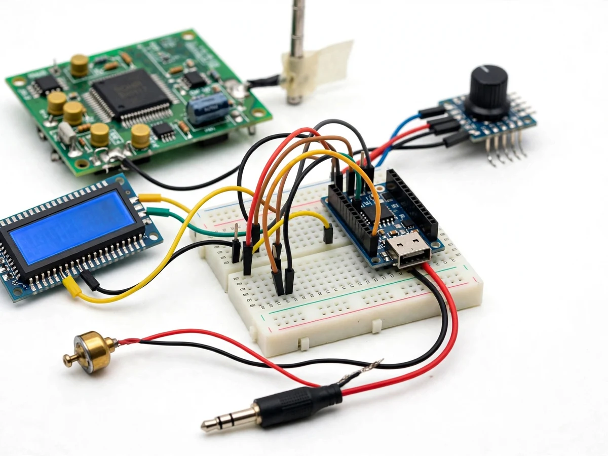
Students study frequency modulation as equations — carrier, deviation, modulation index — but almost never transmit a real FM signal they can tune in on an ordinary radio. The classic student FM transmitter is a single-transistor free-running oscillator that drifts with temperature, hand capacitance and battery voltage, which teaches the wrong lesson about how broadcast FM actually works. This project does it properly: the Rohm BH1417F, a PLL-controlled stereo FM transmitter IC with a built-in stereo modulator, pre-emphasis, limiter and low-pass filter, holds the carrier rock-steady on a crystal reference. An ATtiny/Arduino-class controller programs the BH1417's frequency over its serial interface from a rotary encoder, and a 16×2 LCD shows the exact transmit frequency. The result is a stable, demonstrable stereo FM signal in the 88–108 MHz band that any nearby FM radio can receive — modulation theory made audible.
Electret mic with preamplifier or the 3.5 mm AUX jack feeds program audio into the BH1417.
Follow the working sequence
How it works
- The controller reads the rotary encoder and programs the BH1417's PLL divider over its serial interface, locking the carrier to the selected frequency in 88–108 MHz.
- Audio from the electret mic (via its preamplifier) or the AUX jack is selected and fed to the BH1417's audio inputs.
- Inside the BH1417, the stereo multiplexer encodes left/right into the composite stereo signal with a 19 kHz pilot tone, applies pre-emphasis and limiting.
- The PLL modulates the carrier with the composite signal, holding frequency stable against temperature and supply drift via the crystal reference.
- The modulated RF passes through the matching network to the telescopic whip antenna and radiates as a standard FM broadcast signal.
- Any ordinary FM radio tuned to the displayed frequency receives the transmission in stereo within the demonstration range.
- The LCD continuously shows the carrier frequency so the receiver can be tuned exactly.
Tech stack:
- Rohm BH1417F PLL stereo FM transmitter IC
- ATmega328P / ATtiny controller (frequency programming)
- Rotary encoder with push switch
- 16×2 character LCD
- Electret microphone + preamplifier stage
- 3.5 mm stereo AUX input with level control
- Telescopic whip antenna + matching network
- Low-noise 5 V regulator, 9 V battery / DC adapter
| Parameter | Value |
|---|---|
| Transmit band | 88–108 MHz FM broadcast band |
| Frequency step | 100 kHz (design) |
| Frequency control | PLL with crystal reference (BH1417F) |
| Audio inputs | Electret mic + 3.5 mm stereo AUX |
| Modulation | Stereo multiplex with 19 kHz pilot, 75 µs pre-emphasis (per BH1417F datasheet) |
| RF output | Approximately 10 mW into whip antenna (design target) |
| Demonstration range | Approximately 20–50 m in open conditions (expected, environment-dependent) |
| Supply | 9 V battery or DC adapter, regulated 5 V |
| Display | 16×2 LCD: frequency, source, stereo indicator |
Project features
- [BH1417F PLL transmitter IC] Rohm stereo FM transmitter with on-chip PLL, stereo modulator, pre-emphasis, limiter and low-pass filter — a genuine broadcast-band chip, not a drifting free-running oscillator.
- [Digital frequency setting] Rotary encoder selects the carrier anywhere in 88–108 MHz in 100 kHz steps; the controller programs the BH1417 over its 3-wire serial interface.
- [LCD frequency display] 16×2 LCD shows the exact transmit frequency plus input-source and stereo indicators.
- [Microphone input] Electret condenser microphone with preamplifier for live voice transmission.
- [AUX line input] 3.5 mm stereo jack accepts a phone or laptop as the program source, with an input level control.
- [Whip antenna with matching] Short telescopic antenna with a simple matching network, sized for classroom-scale demonstration range.
- [Regulated power] 9 V battery or DC adapter through a low-noise regulator, with reverse-polarity protection.
- [Labeled enclosure] Vented enclosure with a printed front panel: frequency display window, encoder, input jacks and power switch.
What is included
- Assembled transmitter PCB with BH1417F, controller, LCD and encoder
- Electret microphone, AUX cable and telescopic antenna
- Vented enclosure with labeled front panel
- Controller firmware source (frequency programming, LCD, encoder)
- Schematic, PCB layout notes and RF layout guidelines document
- Regulatory-compliance note for low-power educational transmission
- Project report PDF, PPT presentation and viva Q&A document
Limitations & prerequisites
- This is a short-range educational demonstrator (tens of meters expected); it is not a broadcast station and must be operated within local low-power transmission regulations — a compliance note is included.
- Range is environment-dependent (walls, interference, receiver sensitivity) and is stated as expected, not measured.
- The BH1417F has no RDS/RBDS encoder, so no station-text features; audio is analog stereo only.
- RF performance depends on PCB layout and antenna matching; the kit documents the layout rules, and hand-built units vary.
- Output power and range figures are design targets; the report includes the procedure to verify them on the student's own build.
Frequently Asked Questions
Why the BH1417 instead of a simple transistor transmitter?
A single-transistor oscillator drifts with temperature and touch and transmits in mono. The BH1417 is a PLL-controlled stereo transmitter IC: the carrier stays locked to a crystal reference, and it includes a proper stereo multiplexer, pre-emphasis and limiter — the way real FM works.
How is the frequency set?
A rotary encoder feeds the microcontroller, which programs the BH1417's PLL divider over its serial interface in 100 kHz steps across 88–108 MHz. The LCD always shows the exact carrier so you can tune any FM radio to it.
What can I transmit?
Live voice through the electret mic, or any stereo audio from a phone/laptop through the 3.5 mm AUX jack. The BH1417 encodes it as a standard stereo FM multiplex signal.
How far does it reach?
Approximately 20–50 meters in open conditions is the design expectation — enough for a classroom or lab demo. Walls and interference reduce it; this is stated as expected, not as a measured claim.
Is it legal to operate?
It is a low-power educational device, but broadcast-band rules differ by country. The kit includes a compliance note: operate at the lowest usable setting, for short demonstrations, and check local regulations first.
Is this project suitable for a final-year project?
Yes — for Electronics and Communication programs. It covers PLL frequency synthesis, FM stereo multiplexing, RF layout practice and embedded control in one build. Suitable for B.E./B.Tech final-year projects in Electronics and Communication engineering.
Components & software requirements
- Rohm BH1417F PLL stereo FM transmitter IC
- ATmega328P / ATtiny controller (frequency programming)
- Rotary encoder with push switch
- 16×2 character LCD
- Electret microphone + preamplifier stage
- 3.5 mm stereo AUX input with level control
- Telescopic whip antenna + matching network
- Low-noise 5 V regulator, 9 V battery / DC adapter
Delivery information
Built-to-order project. Delivery timeline is shared after order confirmation based on current queue.
Support terms
Complete documentation, setup guide, and viva preparation included. Support for setup and explanation provided.
Download free synopsis (PDF)
Enter your name and WhatsApp number — the synopsis PDF downloads immediately. We may send occasional project updates on WhatsApp; no spam.