
More project photos (2)
The problem
Every electronics lab needs frequency counters, and few have enough: a commercial 50 MHz counter costs several thousand rupees, so colleges share one or two units across entire batches and students queue for lab hours to check a crystal oscillator or verify a function generator. This project builds a genuinely usable bench counter around the ATmega328P at its standard 16 MHz clock. Below ~10 kHz, Timer1's input-capture hardware measures the signal period against 62.5 ns clock ticks for millihertz-class resolution; above that, direct pulse counting takes over, with an MB506-type ÷64 prescaler bringing the 50 MHz top end down to 781.25 kHz — inside the microcontroller's safe external-clock limit. A 74HC14 Schmitt-trigger stage squares up weak or sine-wave inputs, and the reading updates live on a 16×2 LCD with auto-ranging units. The student who builds it learns timers, prescalers, interrupt handling and measurement error the way no textbook teaches.
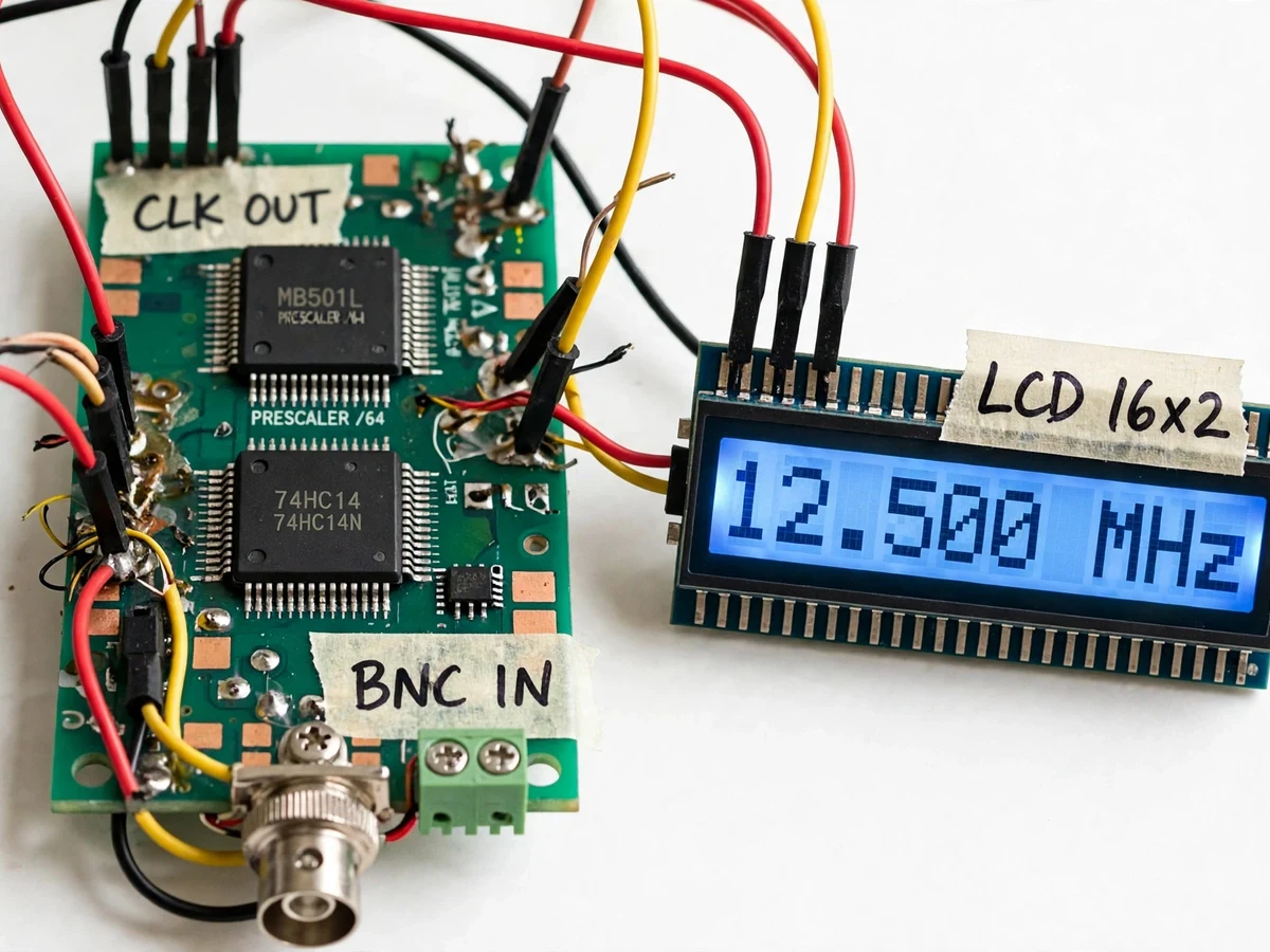
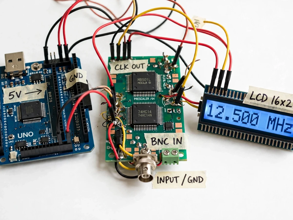
External signal enters through the BNC terminal into the conditioning stage.
Follow the working sequence
How it works
- The signal enters through a BNC / screw-terminal input into the conditioning stage: a 74HC14 Schmitt inverter squares sine and triangle inputs down to ~100 mV pk-pk (design target) into 5 V CMOS edges.
- An input selector routes the signal — 10 Hz to ~10 kHz (approximate band) goes straight to Timer1's input-capture pin; higher frequencies pass through the MB506 ÷64 prescaler first.
- In period mode the 16 MHz system clock gives 62.5 ns ticks, so a 10 Hz signal (100 ms period) is measured as ~1.6 million counts — resolution on the order of 0.001 Hz (theoretical).
- In count mode Timer1 tallies prescaled pulses over the selected gate (1 s gate → 1 Hz resolution); the firmware multiplies the result by 64 to recover the true input frequency.
- The firmware auto-scales units (Hz/kHz/MHz), flags over-range, and refreshes the 16×2 LCD at the end of every gate.
- Calibration mode counts a known reference (for example a 1 MHz tap from a calibrated function generator, buyer-supplied) and stores a trim constant; the ±50 ppm crystal tolerance (datasheet) sets the honest accuracy floor.
Tech stack:
- Arduino Uno (ATmega328P @ 16 MHz)
- MB506-type ÷64 prescaler IC
- 74HC14 Schmitt-trigger conditioning
- 16×2 HD44780 LCD (4-bit interface)
- Timer1 input-capture & external-clock counting
- Embedded C (Arduino framework)
- Perfboard assembly with BNC input
- 5 V regulated DC supply
| Parameter | Value |
|---|---|
| Measurement range | 10 Hz to 50 MHz (design target) |
| Period-measure band | 10 Hz to ~10 kHz (approximate) |
| Gate times | 0.1 s, 1 s, 10 s (selectable) |
| Direct-count resolution | 1 Hz at 1 s gate; 10 Hz at 0.1 s gate |
| Period-mode resolution at 10 Hz | Approximately 0.001 Hz (theoretical) |
| Prescaler | ÷64 (MB506-type); 50 MHz → 781.25 kHz |
| MCU external-clock limit | f_clk/2 = 8 MHz (ATmega328P datasheet) |
| Accuracy floor | ±50 ppm (16 MHz crystal, datasheet) |
| Display | 16×2 HD44780 LCD, auto-ranging Hz/kHz/MHz |
| Input conditioning | 74HC14 Schmitt trigger, ~100 mV pk-pk min (design target) |
| Input connector | BNC / screw terminal |
| Supply | 5 V DC, approximately 150–250 mA (expected) |
Project features
- [Dual-mode measurement engine] Below ~10 kHz (approximate crossover band) the firmware uses Timer1 input capture to measure the signal period against the 16 MHz clock's 62.5 ns ticks; above that it switches to direct pulse counting. Implemented.
- [÷64 prescaler front end] An MB506-type prescaler divides the incoming signal so the 50 MHz top end appears as 781.25 kHz at the microcontroller — safely under the ATmega328P's external-clock limit of f_clk/2 = 8 MHz (datasheet). Implemented.
- [Schmitt-trigger input conditioning] A 74HC14 Schmitt-inverter stage squares up sine and triangle inputs down to ~100 mV pk-pk (design target) into clean 5 V CMOS edges, with hysteresis that keeps noisy sources stable. Implemented.
- [Auto-ranging LCD readout] A 16×2 HD44780 LCD shows the live reading with automatic Hz/kHz/MHz scaling plus a gate-time indicator; over-range is flagged explicitly. Implemented.
- [Selectable gate times] 0.1 s, 1 s and 10 s gates give 10 Hz, 1 Hz and 0.1 Hz direct-count resolution, selectable with a push-button. Implemented.
- [Crystal-referenced calibration] A calibration routine trims the firmware constant against the 16 MHz on-board crystal; absolute accuracy is honestly bounded by the crystal's ±50 ppm tolerance (datasheet). Implemented.
- [Serial logging output] Optional: every reading is also sent over UART, so measurements can be pasted into lab record sheets or plotted later. Optional.
What is included
- Arduino firmware sketch (dual-mode measurement, auto-ranging LCD, calibration routine)
- Input conditioning + prescaler schematic and perfboard layout
- Bill of materials with part numbers and sourcing notes
- Step-by-step calibration procedure against a known reference
- Project report PDF (theory, prescaler math, timer configuration, error analysis)
- PPT presentation for final review
- Viva Q&A preparation document (timers, prescalers, resolution vs accuracy, Schmitt triggers)
Limitations & prerequisites
- Absolute accuracy is bounded by the 16 MHz crystal's ±50 ppm tolerance (datasheet) — about ±2.5 kHz at the 50 MHz top end.
- Direct-count resolution is ±1 count per gate: ±1 Hz at a 1 s gate, ±10 Hz at 0.1 s.
- Without the prescaler board, the T1 pin tops out at ~8 MHz (f_clk/2, datasheet) — the 50 MHz figure needs the prescaler path.
- Input must stay within 0–5 V after conditioning; the ATmega328P pin absolute maximum is 6.0 V (datasheet), so higher-voltage sources need the attenuator stage.
- Sine inputs below ~100 mV pk-pk (design target) may not trigger the Schmitt stage reliably.
- Measures frequency only — no duty cycle, pulse width or phase measurement in this build.
Frequently Asked Questions
How can a 16 MHz Arduino measure 50 MHz?
The MB506-type ÷64 prescaler divides the input before it reaches the microcontroller: 50 MHz becomes 781.25 kHz, comfortably under the ATmega328P's external-clock limit of f_clk/2 = 8 MHz (datasheet). Firmware multiplies the counted value by 64 to recover the true frequency.
Why does it need two measurement modes?
Direct counting has ±1-count resolution, which is ±1 Hz at a 1 s gate — a 10% error at 10 Hz. Period measurement inverts the problem: the 16 MHz clock's 62.5 ns ticks count a 100 ms period as ~1.6 million ticks, giving millihertz-class theoretical resolution at 10 Hz.
What kinds of signals can it measure?
Any periodic signal from 10 Hz to 50 MHz — sine, square or triangle — once squared up by the Schmitt-trigger stage. It reports frequency only, not amplitude, duty cycle or phase.
How accurate is the reading really?
Honestly bounded by the on-board 16 MHz crystal's ±50 ppm tolerance (datasheet): about ±500 Hz at 10 MHz and ±2.5 kHz at 50 MHz. The calibration routine trims firmware error against a known reference; the crystal is the floor.
Can it replace a bench frequency counter in the lab?
For routine checks — oscillator verification, 555 timer frequencies, function-generator calibration, crystal testing — yes, within its stated accuracy. It is not a substitute for a calibrated metrology instrument.
Is this project suitable for a final-year project?
Yes — for Electronics/E&TC programs. It combines timer/counter peripherals, prescaler math, analog signal conditioning and honest measurement-error analysis, with a genuinely usable bench instrument as the outcome.
Components & software requirements
- Arduino Uno (ATmega328P @ 16 MHz)
- MB506-type ÷64 prescaler IC
- 74HC14 Schmitt-trigger conditioning
- 16×2 HD44780 LCD (4-bit interface)
- Timer1 input-capture & external-clock counting
- Embedded C (Arduino framework)
- Perfboard assembly with BNC input
- 5 V regulated DC supply
Delivery information
Built-to-order project. Delivery timeline is shared after order confirmation based on current queue.
Support terms
Complete documentation, setup guide, and viva preparation included. Support for setup and explanation provided.
Download free synopsis (PDF)
Enter your name and email — the synopsis PDF downloads immediately. We may send occasional project updates; no spam, unsubscribe anytime.