
More project photos (2)
The problem
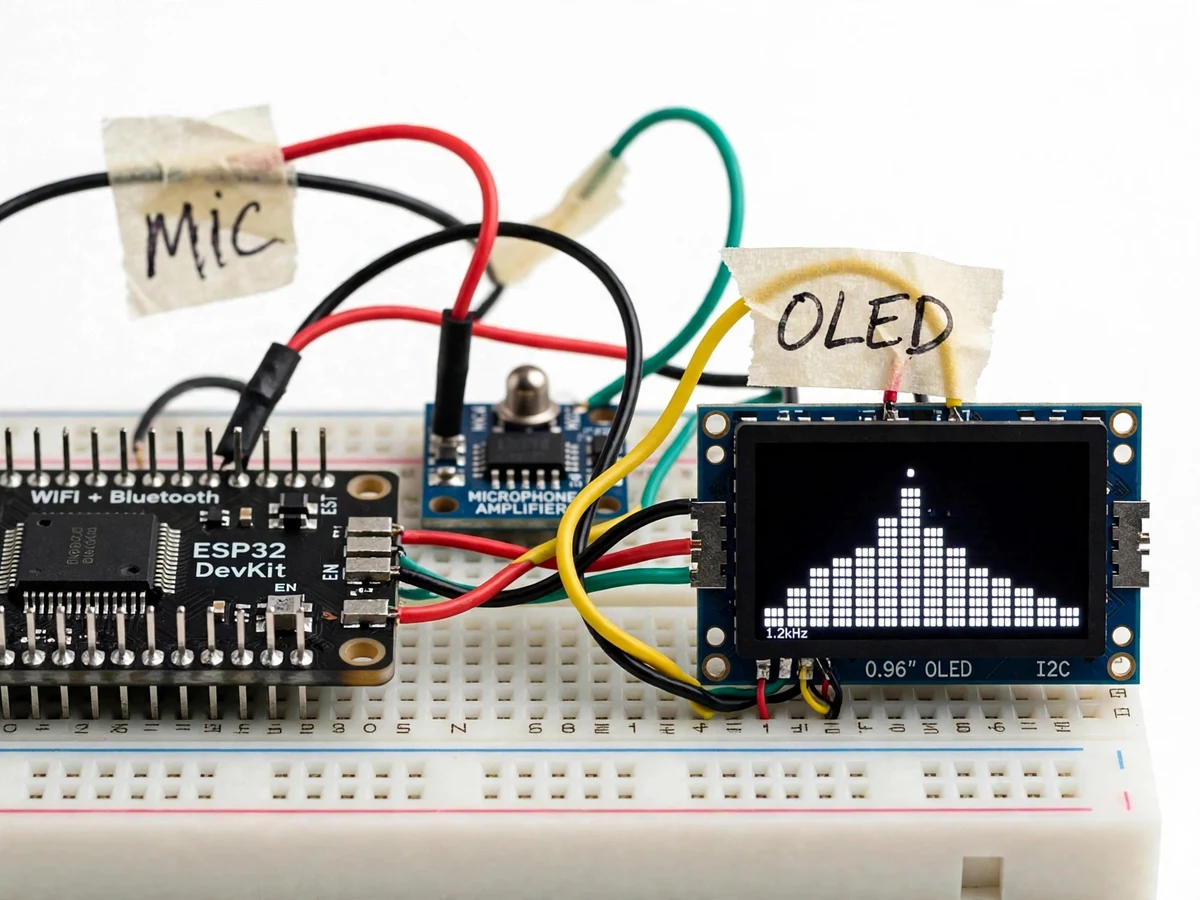
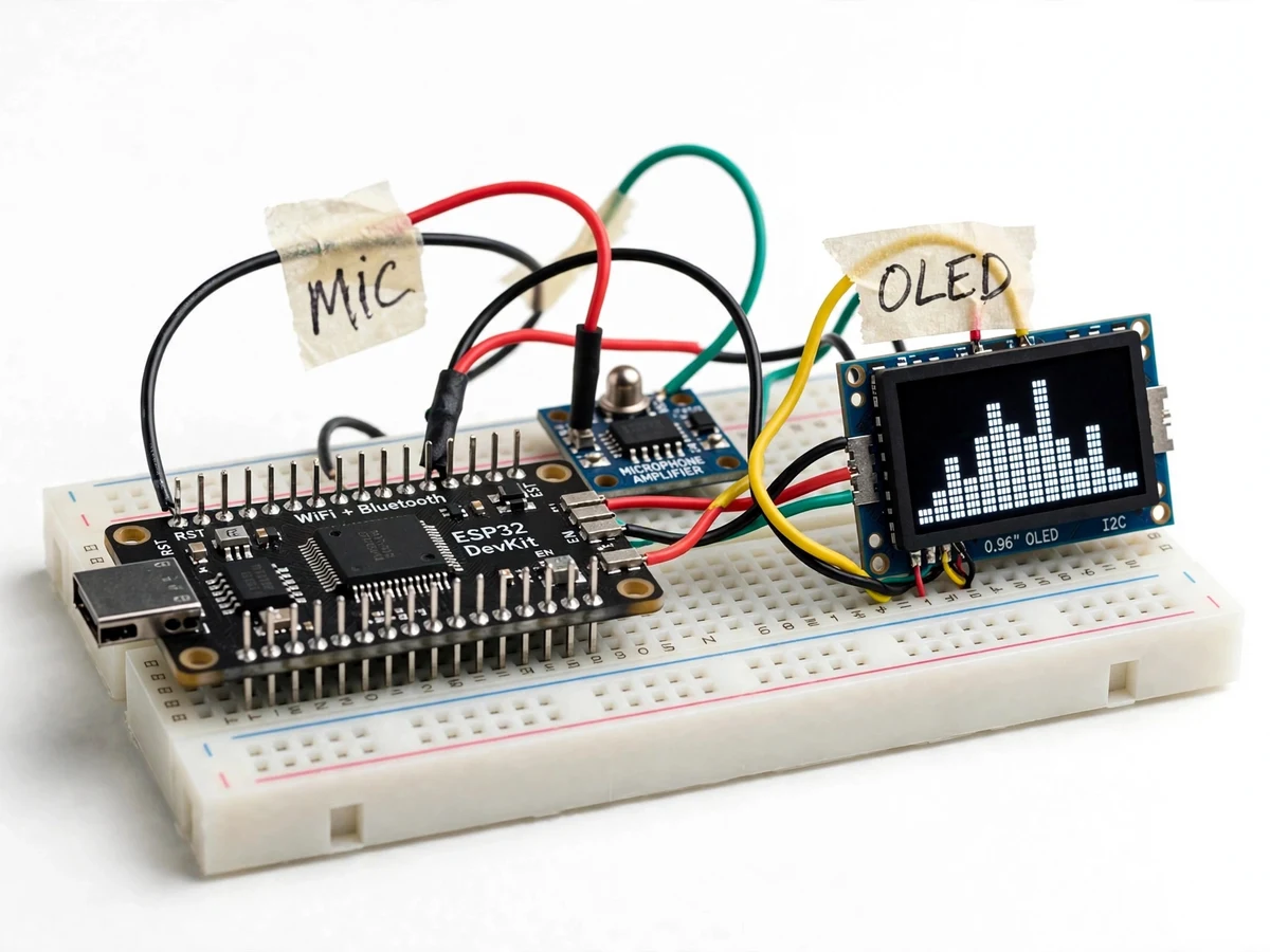
An audio spectrum analyzer shows which frequencies are present in a sound, in real time — the bar-graph display musicians and sound engineers watch on mixers and car stereos. The ESP32 FFT Audio Spectrum Analyzer with OLED Display builds this instrument at student scale: a MAX9814 electret microphone module captures room audio, an ESP32 samples it at about 40 kHz (design target), a 256-point Fast Fourier Transform converts each sample window into 128 frequency bins, and a 0.96-inch OLED draws the result as 16 animated bars with peak-hold dots and a dominant-frequency readout. Students meet the FFT in signals-and-systems courses as pure mathematics; this project turns that mathematics into hardware that responds to claps and music. The whole chain runs on the microcontroller with no PC, Wi-Fi or cloud in the loop, so it demonstrates embedded digital signal processing end to end — sampling, windowing, transforms and display rendering — the skill set E&TC curricula and embedded interviews test for.
Electret capsule with automatic gain control captures room audio.
Follow the working sequence
How it works
Sound enters through the MAX9814 electret microphone module, whose automatic gain control keeps quiet and loud passages within the ESP32's 0–3.3 V ADC window. Firmware samples the 12-bit ADC (datasheet) at about 40 kHz on a timer interrupt until 256 samples are collected — one FFT frame. The arduinoFFT library strips the DC offset, applies a Hamming window to suppress spectral leakage, and computes the 256-point transform; magnitude conversion yields 128 usable frequency bins spanning 0–20 kHz, each about 156 Hz wide. Adjacent bins are grouped into the 16 bars that fit the 128×64 SSD1306 OLED, peak-hold markers freeze momentary transients, and majorPeak interpolation reads out the dominant frequency with sub-bin resolution. The display redraws every completed frame, so claps, whistles and music appear as a living spectrum — the entire pipeline, from acoustic pressure wave to pixels, executes on the single ESP32 board.
Builder notes from the actual design: DC removal runs before the Hamming window for a first-principles reason — a DC offset dumps all its energy into bin 0, and leaving it in inflates the lowest bars of every frame. The MAX9814's output rides on a ~1.25 V DC bias (Adafruit MAX9814 module documentation), so subtracting the frame's mean first is what makes the AC bars honest. And the ~40 kHz sampling rate is an anti-aliasing choice, not a round number: it puts the Nyquist ceiling at 20 kHz, above both the plotted range and the mic module's useful band, so every bar shows content actually present in the signal rather than aliases folded back from above Nyquist.
- The MAX9814 module's electret capsule captures sound; its AGC amplifier outputs AC audio riding on a ~1.25 V DC bias into an ESP32 ADC input (GPIO 34, ADC1 — free of the Wi-Fi conflict that affects ADC2).
- A timer-interrupt routine samples the 12-bit ADC at about 40 kHz (design target) until 256 samples are collected, giving one FFT frame.
- Firmware subtracts the frame's mean (DC removal) and applies a Hamming window, then the arduinoFFT library computes the 256-point forward transform.
- ComplexToMagnitude converts the result into 128 frequency bins spanning 0–20 kHz — each bin about 156 Hz wide, derived from the design values.
- Adjacent bins are summed into 16 display bars; a noise gate drops bars below the ambient floor, peak-hold markers decay from their maxima, and majorPeak interpolates the dominant frequency.
- The SSD1306 OLED redraws the 16 bars, peak markers and the frequency readout every completed frame, rendering the live spectrum.
Tech stack:
- ESP32 DevKit V1 · dual-core Xtensa firmware in C++
- arduinoFFT library (kosme) · 256-point FFT + DC removal + Hamming window
- Adafruit SSD1306 + Adafruit GFX · 0.96" OLED driver over I2C
- MAX9814 electret microphone module · AGC
- ESP32 12-bit ADC · ~40 kHz timer-interrupt sampling
- Arduino IDE · firmware development, serial monitor
- Solderless breadboard + jumper wires · prototype assembly
- 5 V USB power · micro-USB cable
| Parameter | Value |
|---|---|
| Controller | ESP32 DevKit V1 (dual-core Xtensa, up to 240 MHz — datasheet) |
| Microphone | MAX9814 electret module, AGC, 2.7–5.5 V supply (datasheet) |
| ADC | 12-bit SAR, 0–3.3 V input range (datasheet) |
| Sampling rate | ~40 kHz, timer-interrupt driven (design target) |
| FFT | 256-point, Hamming window, DC removal (design) |
| Frequency range | 0–20 kHz (Nyquist at ~40 kHz sampling — design) |
| Bin resolution | ~156 Hz per bin (derived from design values) |
| Display | 0.96" 128×64 OLED, SSD1306, I2C address 0x3C typical (datasheet) |
| Display rendering | 16 spectrum bars + peak-hold markers + dominant-frequency readout (design) |
| Power | 5 V USB, approximate 100–240 mA active (typical) |
Project features
The analyzer's capabilities are seven. First, the microphone stage: a MAX9814 electret module with automatic gain control feeds the ESP32's ADC, so quiet and loud sounds stay inside the 0–3.3 V conversion window without manual adjustment. Second, the DSP core: a genuine 256-point FFT computed on the ESP32 by the arduinoFFT library (kosme/arduinoFFT on GitHub), with DC removal and Hamming windowing applied before every transform — the same mathematics taught in signals-and-systems courses, running on silicon. Third, the display: a 0.96-inch 128×64 SSD1306 OLED renders 16 animated spectrum bars spanning 0–20 kHz (design values). Fourth, peak-hold with decay freezes the tallest transient on each bar so claps and drum hits remain visible after the sound dies. Fifth, the dominant-frequency readout reports the strongest bin with parabolic interpolation for sub-bin resolution. Sixth, an adjustable noise gate suppresses ambient hiss below a set floor. Seventh, the entire instrument runs from 5 V USB with no PC, Wi-Fi or internet required.
- [Electret microphone input with AGC] A MAX9814 microphone module (electret capsule + automatic gain control, 2.7–5.5 V supply — datasheet) captures room audio and keeps its output within the ESP32 ADC's 0–3.3 V window across quiet and loud sounds, so no manual gain knob is needed during demos.
- [256-point FFT on the ESP32] Firmware computes a real 256-point Fast Fourier Transform with the arduinoFFT library (kosme/arduinoFFT, installable from the Arduino Library Manager) — DC removal, Hamming windowing, forward transform, and magnitude conversion, all executed on the microcontroller.
- [16-bar live spectrum on OLED] A 0.96-inch 128×64 SSD1306 OLED (I2C, address 0x3C typical — datasheet) renders 16 animated vertical bars covering 0–20 kHz, with about 156 Hz per FFT bin derived from the 40 kHz sampling and 256-point design values.
- [Peak-hold with decay] Each bar keeps a small marker at its recent maximum that decays downward over time, so transient peaks (claps, snare hits) stay visible long enough to read while the live bars keep dancing.
- [Dominant-frequency readout] The firmware's majorPeak routine interpolates the strongest bin with a parabola and prints the dominant frequency on the OLED, turning the analyzer into a rough frequency counter for tones and whistles.
- [Adjustable noise gate] A firmware-settable magnitude floor ignores bins below the ambient-hiss level, so the display sits quiet in a silent room and only bars rise above the gate when real sound is present.
- [Fully standalone operation] The instrument runs from 5 V USB power on one ESP32 DevKit board — no PC, no Wi-Fi and no internet is required, which keeps the demo working in any lab or viva room.
What is included
- Assembled prototype (ESP32 DevKit + MAX9814 mic module + 0.96" OLED, wired on breadboard or perfboard base)
- ESP32 firmware source with comments (sampling, FFT, OLED rendering, noise gate, peak-hold)
- Wiring diagram and pin-connection table
- Builder notes: DC-removal rationale, anti-aliasing sample-rate choice, ADC input notes
- Project report PDF (DSP background, FFT theory, methodology, design values, demonstration results from your own build)
- PPT presentation for final review
- Viva Q&A preparation document (FFT, windowing, Nyquist, aliasing, bin resolution, ADC, peak-hold)
Limitations & prerequisites
- This is a relative spectrum display, not a calibrated SPL meter — bar heights show relative energy per band, and no decibel claim is made without a buyer-run calibration against a known source.
- The ~156 Hz bin width (derived from design values) cannot resolve closely spaced tones; semitone-level pitch detail and chord analysis are out of scope — a 512-point FFT build is an optional customization.
- Very loud sounds can clip the microphone output; the AGC recovers, but clipped frames produce harmonics that were not in the original sound — the report documents this honestly.
- The ESP32 ADC is noisier near its 0 V and 3.3 V rails; the design keeps the mic signal near mid-rail, and accuracy below the noise floor is not claimed.
- Timer-interrupt sampling can jitter if background tasks run long; the firmware keeps the sampling ISR minimal, but the rate is stated as a design target, not a measured guarantee.
- The 128×64 OLED is the complete display — there is no spectrum history recording, no audio output, and no frequency data logging in the base build.
- This is an academic demonstration prototype, not a measurement instrument and not certified for any acoustic compliance use.
Frequently Asked Questions
Is the FFT real, or just an animated display?
Real. The firmware collects 256 ADC samples per frame and computes a genuine Fast Fourier Transform with the arduinoFFT library (kosme/arduinoFFT, installable from the Arduino Library Manager). What you see on the OLED is the magnitude of the actual sound in the room — feed it a 1 kHz tone from a phone app and watch the bar near 1 kHz rise.
Is this AI or machine learning?
No. The FFT is classical digital signal processing mathematics — no model is trained and nothing learns. It is honest DSP on a microcontroller, which is exactly the point: the project demonstrates transforms, windowing and sampling theory from the signals-and-systems syllabus on real hardware.
How precise is the frequency display?
Each of the 128 FFT bins is about 156 Hz wide (derived from the ~40 kHz sampling and 256-point design values), and the majorPeak interpolation refines the dominant-frequency readout between bins. The report documents a buyer-run check procedure using a tone-generator phone app so the student measures the readout against known tones.
Does it need Wi-Fi or the internet?
No. The entire build — ADC sampling, FFT computation and OLED rendering — runs on the ESP32 from 5 V USB power with no network of any kind, so the demo works in any lab, classroom or viva room without connectivity.
What power supply does it need?
Any 5 V USB source — a laptop port, a phone charger or a power bank. Active current draw is approximate 100–240 mA (typical), so a small power bank runs the instrument through hours of continuous demonstration without a wall socket.
Is this project suitable for a final-year project?
Yes — for Electronics and Telecommunication programs. It demonstrates microphone interfacing, ADC sampling, timer interrupts, the FFT and windowing computed on real hardware, plus OLED display rendering — a complete embedded-DSP build the student can genuinely defend in the viva.
Components & software requirements
- ESP32 DevKit V1 · dual-core Xtensa firmware in C++
- arduinoFFT library (kosme) · 256-point FFT + DC removal + Hamming window
- Adafruit SSD1306 + Adafruit GFX · 0.96" OLED driver over I2C
- MAX9814 electret microphone module · AGC
- ESP32 12-bit ADC · ~40 kHz timer-interrupt sampling
- Arduino IDE · firmware development, serial monitor
- Solderless breadboard + jumper wires · prototype assembly
- 5 V USB power · micro-USB cable
Delivery information
Built-to-order project. Delivery timeline is shared after order confirmation based on current queue.
Support terms
Complete documentation, setup guide, and viva preparation included. Support for setup and explanation provided.
Download free synopsis (PDF)
Enter your name and WhatsApp number — the synopsis PDF downloads immediately. We may send occasional project updates on WhatsApp; no spam.