
More project photos (2)
The problem
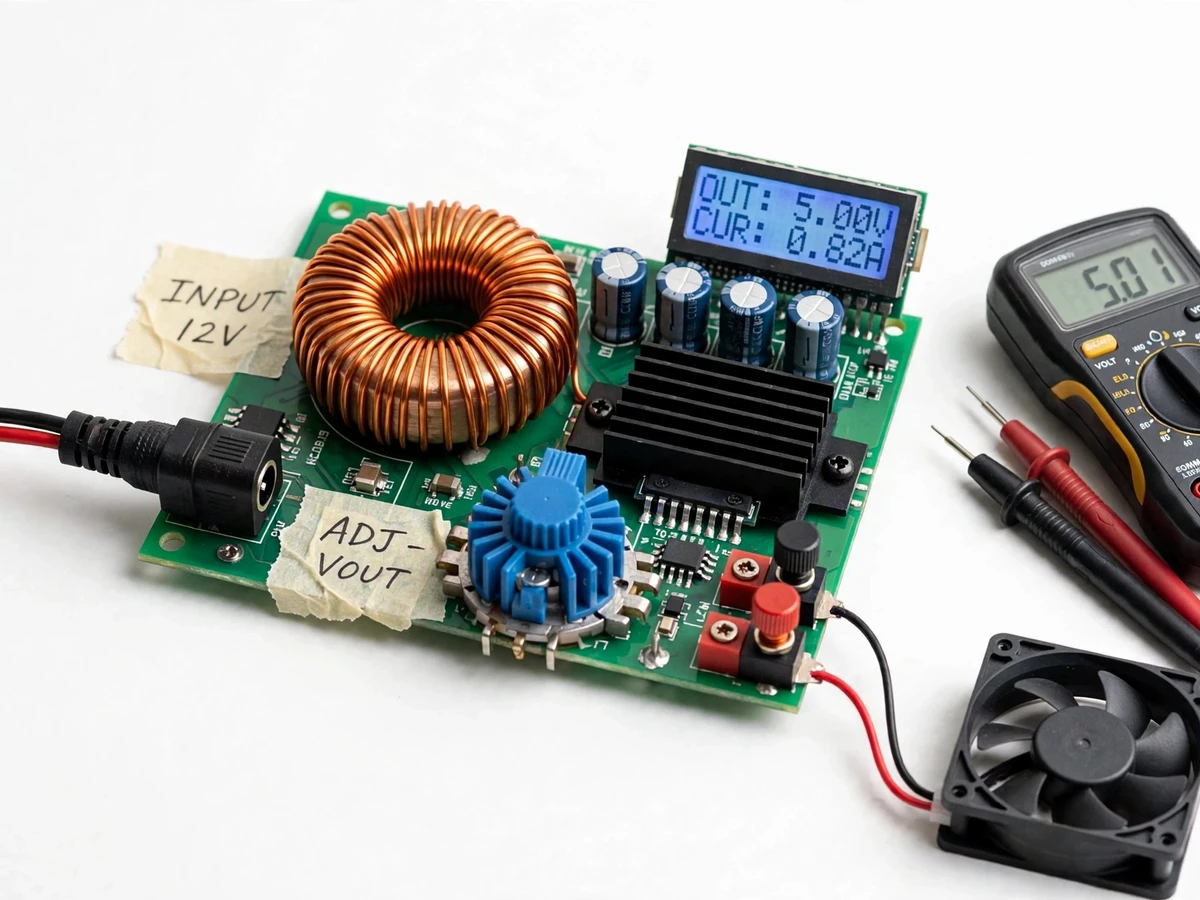
The DIY buck converter project answers a gap on most student benches, where fixed chargers and adapters — one for every voltage a circuit needs — teach nothing about how a regulated supply actually works. A linear regulator can drop voltage, but it burns the difference as heat, so it runs hot and wastes power whenever the input-output gap is large. It is an adjustable DC-DC step-down supply built around an LM2596 switching regulator, with a potentiometer that sets the output voltage and an LCD display with voltage and current readout. Students can dial 3.3 V for a microcontroller board, 5 V for a sensor module, or a higher rail for a small motor, and watch the regulator hold that voltage as the load changes. The project is useful because almost every electronics prototype needs a clean, adjustable supply, and building one turns an abstract power-electronics topic into a testable bench tool for later bench use.
A 12 V to 24 V DC supply feeds the regulator.
Follow the working sequence
How it works
The DIY buck converter project works end to end as a complete step-down power chain, from DC input to regulated adjustable output with an LCD readout. A 12 V to 24 V DC source feeds the LM2596 regulator, which switches the input on and off at its 150 kHz datasheet frequency. Duty cycle, the fraction of each period the switch stays on, sets the average output voltage: ideally, output voltage equals duty cycle multiplied by input voltage, before losses. An inductor and output capacitor filter that waveform, storing energy in the on-time and releasing it in the off-time, so the load sees smooth DC. A feedback divider samples the output and returns it to the regulator, which trims the duty cycle to hold the voltage the potentiometer selected. An Arduino Nano separately measures output voltage and current for the LCD display, giving a live check while a load runs.
- A DC input supply, typically 12 V to 24 V, is connected to the labelled input terminals, with input capacitors smoothing the incoming rail.
- The LM2596 switching regulator chops the input at its 150 kHz datasheet switching frequency, producing a pulsed waveform whose duty cycle sets the average output level.
- The inductor stores energy while the switch is on and releases it while the switch is off, and the output capacitor smooths the result into steady DC.
- A feedback divider samples the output voltage and feeds it back to the regulator, which adjusts the duty cycle to hold the selected voltage.
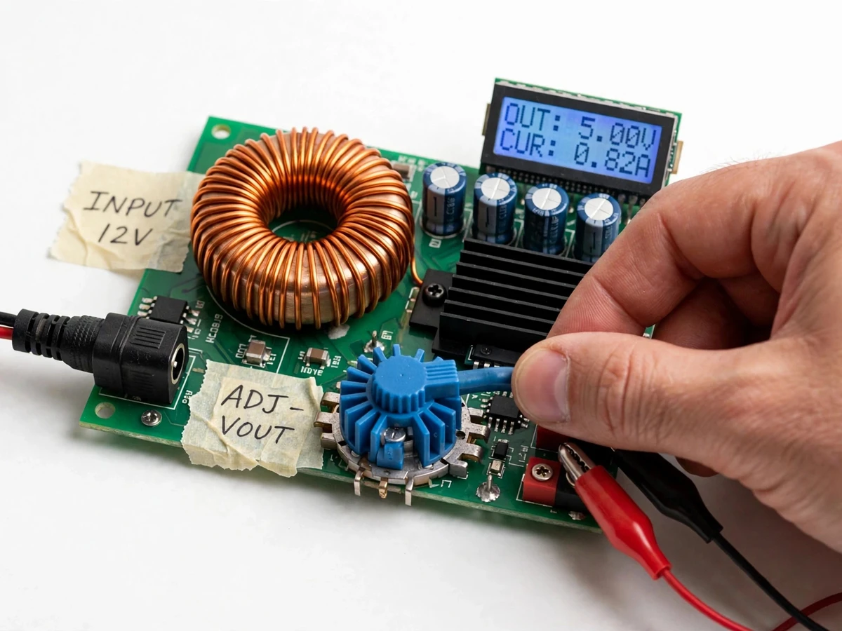
- Turning the potentiometer changes the divider ratio, so the regulator settles at a new output voltage, which the user verifies on the LCD.
- The Arduino Nano measures output voltage through a divider and load current through a current-sense module, and updates the 16x2 LCD display with both readings.
- The regulated output is delivered through labelled output terminals to the load, such as a microcontroller board, sensor module or small DC motor, while the display and a multimeter confirm behaviour under load.
Tech stack:
- LM2596 switching regulator
- Arduino Nano · LCD readout
- Toroidal inductor · LC filter
- 16x2 character LCD display
- Potentiometer feedback divider
- ACS712 current-sense module
- DC input terminals · test load
- Multimeter verification procedure
| Parameter | Value |
|---|---|
| Regulator | LM2596 step-down switching regulator (datasheet values: input up to 40 V · output current up to 3 A · fixed switching frequency 150 kHz · feedback reference 1.23 V) |
| Input voltage | 12 V to 24 V DC (design target) |
| Output voltage | Adjustable from approximately 3.3 V to 12 V (design target · always below the input voltage) |
| Output current | Up to 3 A (datasheet maximum for the LM2596 · continuous use below this limit is recommended) |
| Switching frequency | 150 kHz (datasheet value) |
| Duty cycle example | Approximately 0.42 for 5 V output from 12 V input in the ideal relation Vout = D x Vin (approximate · before losses) |
| Filter components | 100 uH inductor (design target) · 470 uF output capacitor (design target) |
| Display | 16x2 character LCD showing output voltage in V and load current in A |
| Measurement | Arduino Nano with resistor divider for voltage and ACS712 module for current (approximate readings · verified against a multimeter) |
| Protection | Current limiting and thermal shutdown (datasheet features of the LM2596) |
| Output terminals | Labelled red and black binding-post terminals for load connection |
| Builder note | The feedback divider follows Vout = 1.23 V x (1 + R2 / R1) from the LM2596 datasheet reference; the output capacitor was sized large enough to keep ripple low at 150 kHz while accepting a slower transient response, and the regulator is mounted with a heatsink and airflow clearance because sustained high-current operation still produces heat |
Project features
The DIY buck converter project is built around four capabilities that matter most on a student bench. First, adjustable output voltage: a potentiometer in the feedback path sets the output across the design-target range, so one supply serves 3.3 V logic, 5 V modules and other low-voltage loads without swapping adapters. Second, live LCD readout: the display shows output voltage and load current together, so voltage setting and load behaviour can be checked at a glance during testing. Third, closed-loop feedback regulation: the regulator continuously compares a divided sample of the output against its internal reference and adjusts switching to hold the set voltage when input or load changes. Fourth, a switching power stage with inductor-capacitor filtering: the LM2596 switches at a fixed datasheet frequency and the LC filter smooths that switched waveform into steady DC, which is why the converter runs cooler than a linear regulator dropping the same voltage.
- [Adjustable output voltage] A potentiometer in the feedback divider sets the output voltage across the design-target range, so one supply can serve 3.3 V, 5 V and other low-voltage loads without changing adapters.
- [LCD voltage and current readout] A 16x2 LCD, driven by an Arduino Nano that samples the output through a voltage divider and a current-sense module, displays output voltage and load current together during testing.
- [Closed-loop feedback regulation] The regulator continuously compares a divided sample of the output against its 1.23 V datasheet reference and adjusts its switching duty cycle to hold the set voltage when input voltage or load current changes.
- [Switching power stage with LC filtering] The LM2596 switches the input through an inductor and output capacitor, which smooth the switched waveform into steady DC with less heat than a linear regulator dropping the same voltage.
- [Overload and thermal protection] The LM2596 provides datasheet current limiting and thermal shutdown, so a shorted output or an overheated regulator shuts down instead of destroying the board.
- [Bench test terminals] Clearly labelled input and output terminals, plus a fixed test load connection, let students connect a multimeter, a microcontroller board or a small motor and verify the supply under load.
- [Low-ripple output design] A design-target 100 uH inductor and 470 uF output capacitor were chosen to keep output ripple low at the regulator switching frequency, with the trade-off between ripple, size and transient response documented in the report.
What is included
- Assembled DIY buck converter prototype: LM2596 power stage, inductor and capacitors, heatsink, potentiometer adjustment, LCD display unit and labelled input/output terminals
- Arduino Nano LCD readout firmware with voltage-divider and current-sense measurement code
- Circuit diagram, wiring layout and feedback-divider calculation notes
- Component list with values, ratings and sourcing notes
- Test procedure: no-load voltage setting, loaded voltage check, ripple observation and multimeter cross-check
- Project report PDF (power-electronics background, switching theory, design calculations, test procedure, results discussion)
- PPT presentation for final review
- Viva Q&A preparation document (buck operation, duty cycle, inductor and capacitor roles, feedback control, linear versus switching regulation)
- Build timeline: approximately 2 to 3 weeks from component sourcing to tested prototype and documentation (expected)
- Support: build guidance, test-procedure walkthrough and documentation corrections during the project period (as agreed at order)
Limitations & prerequisites
- The output voltage must always stay below the input voltage; a buck converter cannot step voltage up, so a 5 V output needs an input above approximately 5 V.
- Output current is limited by the LM2596 datasheet maximum of 3 A, and sustained operation near that limit needs heatsinking and airflow; it is not a high-power bench supply.
- LCD current and voltage readings are approximate measurement aids, not calibrated instrument readings; final verification should use a multimeter.
- Output ripple is low by design but not zero; ripple-sensitive analogue circuits may still need additional local filtering at the load.
- Efficiency varies with input-output voltage gap and load current, and no efficiency figure is claimed without a measured test for the delivered build.
- The prototype is an academic bench supply, not a certified mains power supply; it runs from a DC input only and must not be connected directly to mains AC.
- Component values are design targets: inductor and capacitor choice trades ripple against size, cost and transient response, and the report documents those trade-offs.
Frequently Asked Questions
Is this project suitable for a final-year project?
Yes, this project suits Electrical and Electronics final-year work because it covers power electronics, feedback control, switching regulation and practical measurement in one testable build. It gives students a working bench supply plus design calculations, a test procedure and results to discuss, rather than only a simulation or a block diagram. The report documents the duty-cycle relation, the feedback-divider calculation and the ripple trade-off, so the work stands up to detailed questioning.
Which controller is used, and why?
The LM2596 switching regulator is used because it is a widely available, documented step-down controller with a fixed 150 kHz switching frequency, a 1.23 V feedback reference and built-in current limiting and thermal shutdown. It needs only an inductor, a diode, input and output capacitors and a feedback divider around it, which keeps the student build understandable and repairable. The Arduino Nano is used only for the LCD readout, not for the power regulation itself.
What power supply do I need to run it?
A DC input supply of 12 V to 24 V is the design-target input range, such as a standard 12 V DC adapter or a bench DC supply, and the output must always stay below the input voltage. No mains connection is made to the prototype itself, and the input must be DC only, never AC mains. A multimeter is recommended alongside the LCD so students can cross-check the displayed voltage and current during testing.
How accurate is the output voltage, and how much ripple is there?
The output voltage is held by closed-loop feedback, so it stays close to the set value as load changes, within the limits of component tolerances and the approximate LCD measurement chain. Ripple is kept low by the design-target 100 uH inductor and 470 uF output capacitor, but it is not zero and is not claimed as a measured figure. The test procedure shows students how to observe ripple and loaded voltage themselves with a multimeter.
Can this project be customized?
Yes, realistic customizations include a second output rail, preset voltage selector switches, a digital up/down voltage control in place of the potentiometer, USB output terminals, or a logged voltage-versus-time test record. Each option is developed separately from the base build, with its cost and timeline agreed before work starts. Customizations that change the power stage, such as a higher current rating, need a regulator and component review first.
What will I receive with the project?
You receive the assembled buck converter prototype with LCD display, the Arduino Nano readout firmware, the circuit diagram and wiring layout, the component list, the test procedure and the complete viva kit of report, PPT and Q&A document. The prototype is delivered tested at no-load and under a small test load, with the voltage-setting and multimeter cross-check procedure included. Documentation corrections and build guidance during the project period are included as agreed at order.
Components & software requirements
- LM2596 switching regulator
- Arduino Nano · LCD readout
- Toroidal inductor · LC filter
- 16x2 character LCD display
- Potentiometer feedback divider
- ACS712 current-sense module
- DC input terminals · test load
- Multimeter verification procedure
Delivery information
Built-to-order project. Delivery timeline is shared after order confirmation based on current queue.
Support terms
Complete documentation, setup guide, and viva preparation included. Support for setup and explanation provided.
Download free synopsis (PDF)
Enter your name and WhatsApp number — the synopsis PDF downloads immediately. We may send occasional project updates on WhatsApp; no spam.