
More project photos (2)
Watch it work
The problem
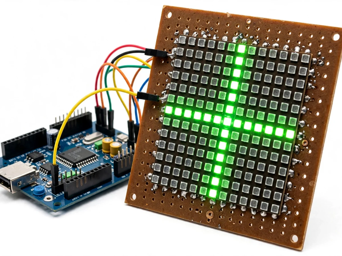
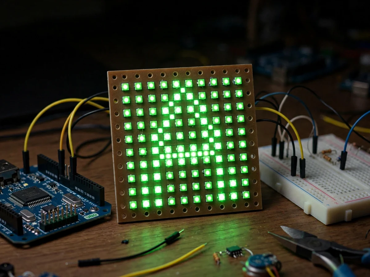
This DIY 8x8 LED matrix display is a tabletop student build that turns 64 LEDs into a display you can program: an Arduino Uno drives the grid row by row, switching the LEDs on and off so fast that the eye sees a full picture, and the firmware cycles through patterns and scrolls text across the board. There is no computer attached while it runs — the display driving, the pattern logic and the scrolling text all run on the microcontroller. The demonstration starts with the board itself, shows the hand-soldered wiring on the back, runs the patterns on the bench, and then scrolls text in the dark where the letters are brightest.
How it works
From switch-on to scrolling text takes five stages a student can trace and test. The builder solders the 64 LEDs into 8 rows and 8 columns on the perfboard and wires each row and column back to the Arduino. The firmware then scans the rows in turn, setting the column lines for the row that is lit, and cycles through the rows fast enough that the eye sees a whole pattern. Patterns run first, each one held long enough to read, and then the text scrolls across the grid one column at a time — brightest in the dark, where the demonstration films it.
- The builder assembles the display: 64 green LEDs on a perfboard, wired row by row and column by column to an Arduino Uno on a breadboard, powered from a 5 V USB supply.
- The builder checks the wiring alone: every row and column is tested for continuity, so a dead LED or a short is found before the Arduino is connected.
- The builder checks the row-column driving alone: the firmware lights one row at a time and the scan is confirmed by eye, so a wiring fault is caught before the display logic is blamed.
- The builder checks the patterns alone: a set of patterns is cycled on the board and each one is checked against what the code intended.
- The builder records the demonstration run: the board front and back, the patterns on the bench, and the scrolling text in the dark, all visible in the video.
Tech stack:
- Arduino Uno · ATmega328P microcontroller
- 8x8 LED matrix · 64 green LEDs on perfboard
- Row-column multiplexing · display driving method
- Breadboard prototype · jumper wiring
- Embedded C · Arduino IDE firmware
- 5V USB power · bench supply
| Parameter | Value |
|---|---|
| Controller | Arduino Uno · ATmega328P · 16 MHz · 2 KB SRAM (Datasheet value) |
| Display | 8x8 LED matrix · 64 green LEDs · perfboard build |
| Driving | Row-column multiplexing · one row lit at a time |
| Display modes | Sweeping patterns · scrolling text |
| Text | Short words and symbols · longer messages scroll |
| Power | 5 V USB · bench supply |
| Build style | Hand-soldered perfboard · breadboard prototype |
| Colour | Green LEDs only in the base build |
Project features
The display works because every part of it is visible on one small board. The Arduino scans the rows in turn and sets the column lines for each row, so a pattern or a letter appears on the grid even though only one row is lit at any instant. The board, the wiring and the scrolling text are all shown in the demonstration, which makes the build easy to explain piece by piece in a review.
- [64-LED matrix on perfboard] Sixty-four green LEDs soldered in 8 rows by 8 columns on a single perfboard, so the whole display is one hand-built board — implemented in the base build.
- [Row-column multiplexing] The Arduino lights one row at a time and cycles through all eight rows fast enough for the eye to see a complete picture, so 64 LEDs run from a few Arduino pins — implemented in the base build.
- [Sweeping patterns] A set of patterns sweeps across the board one after another on the bench, so the display logic is visible as movement rather than a static glow — implemented in the base build.
- [Scrolling text] Text scrolls across the grid one column at a time and reads clearly in the dark, so the matrix works as a small message display as well as a pattern board — implemented in the base build.
- [Board shown front and back] The demonstration turns the board over to show the hand-soldered wiring underneath, so the row and column connections can be traced — implemented in the base build.
- [Breadboard prototype] The matrix connects to an Arduino Uno on a breadboard with jumper wiring, so every connection can be traced and re-wired on the bench — implemented in the base build.
What is included
- Working perfboard matrix (64 green LEDs, row and column wiring) with Arduino Uno and breadboard wiring
- Arduino firmware with the pattern set and scrolling text (row scanning, pattern cycling, text scrolling)
- Wiring diagram and perfboard layout documentation
- Component list with part references
- Test and demonstration procedure (wiring check, row scan check, pattern check, scrolling-text check)
- Project report PDF (multiplexing, display driving, demonstration results, honest measurement limits)
- PPT presentation for final review
- Viva Q&A preparation document (how row-column multiplexing works, why only one row is lit at a time, how scrolling text is drawn, what limits an 8 by 8 grid)
Limitations & prerequisites
- Short messages only: the display is 8 by 8, so only short words and simple symbols fit at one time and longer messages must scroll.
- Green only: the base build uses green LEDs, so there is no colour in the display; a multi-colour version needs different LEDs and more wiring.
- Bright daylight: the patterns are clear on the bench but harder to see in bright daylight; the scrolling text reads best in the dark, as shown in the demonstration.
- Hand-soldered prototype: the board is a hand-soldered perfboard build for the bench, not an enclosed consumer display, and it must be handled carefully and kept on a table while running.
- Tabletop model, not certified: this is a student prototype for learning and demonstration, not a commercial display product, and it is not tested or certified for sale as a consumer device.
Frequently Asked Questions
Is this project suitable for a final-year project?
Yes, for Electronics, Electrical and IoT programmes, because it combines display driving, multiplexing and embedded firmware on a single microcontroller into one testable loop, with a clear review thread around driving 64 LEDs from a few pins.
How does the Arduino drive 64 LEDs from a few pins?
By row-column multiplexing: the firmware lights one row at a time and cycles through all eight rows so quickly that the eye sees a complete picture, even though only one row is lit at any instant.
What does the display show?
A set of sweeping patterns on the bench, and scrolling text that reads clearly in the dark. Both are shown working in the demo video.
Can it show longer messages?
Yes, by scrolling: longer text moves across the grid one column at a time. Only short words fit on the 8 by 8 grid at once.
What will I receive with the project?
The working perfboard matrix with Arduino Uno and breadboard wiring, the firmware with the patterns and scrolling text, the wiring diagram and component list, the test and demonstration procedure, the project report, the presentation and the viva Q&A document. A 5 V USB supply and a laptop for uploading the firmware are needed, both covered in the setup guide.
Components & software requirements
- Arduino Uno · ATmega328P microcontroller
- 8x8 LED matrix · 64 green LEDs on perfboard
- Row-column multiplexing · display driving method
- Breadboard prototype · jumper wiring
- Embedded C · Arduino IDE firmware
- 5V USB power · bench supply
Delivery information
Built-to-order project. Delivery timeline is shared after order confirmation based on current queue.
Support terms
Complete documentation, setup guide, and viva preparation included. Support for setup and explanation provided.
Download free synopsis (PDF)
Enter your name and WhatsApp number — the synopsis PDF downloads immediately. We may send occasional project updates on WhatsApp; no spam.