
More project photos (2)
The problem
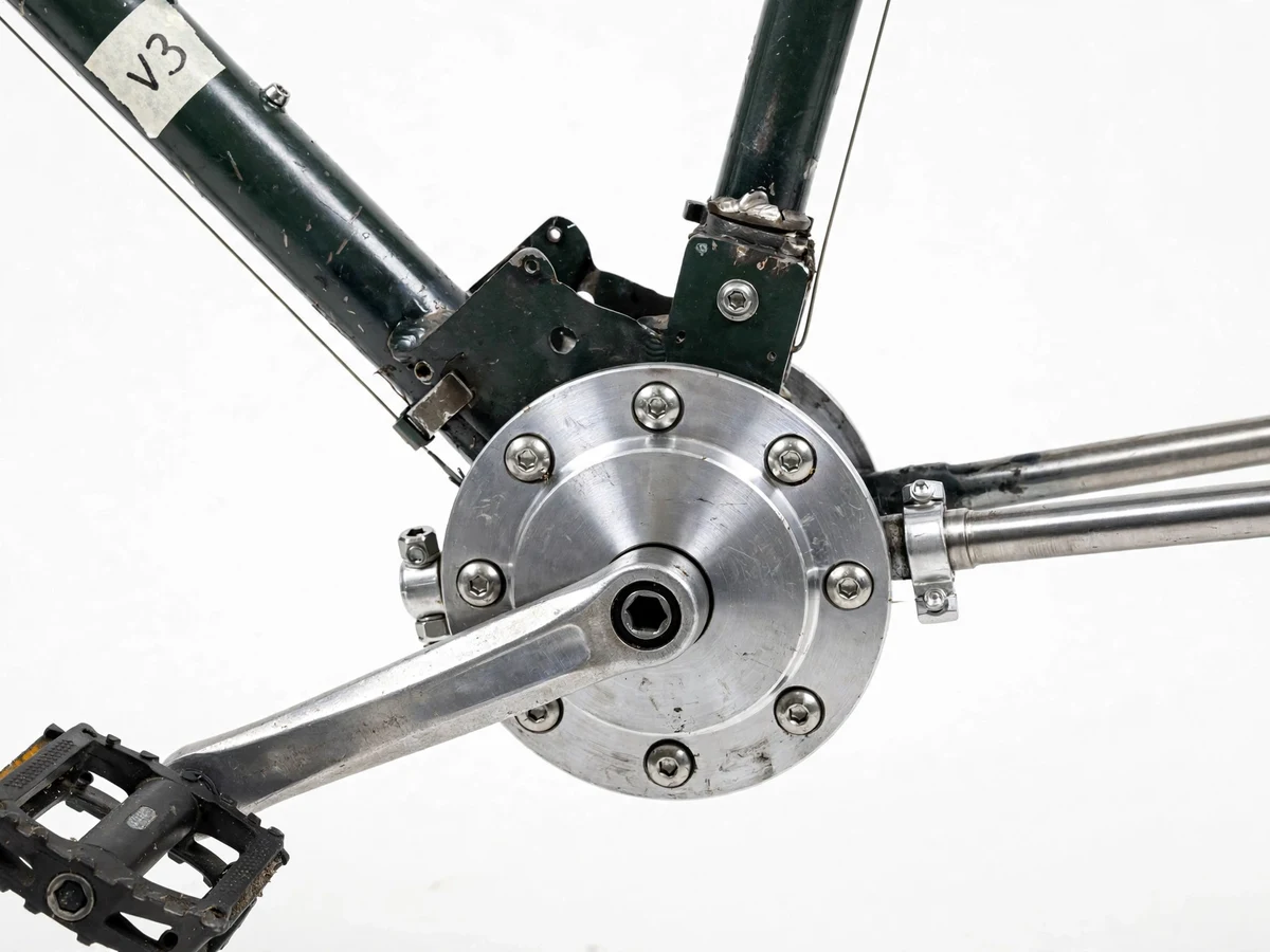
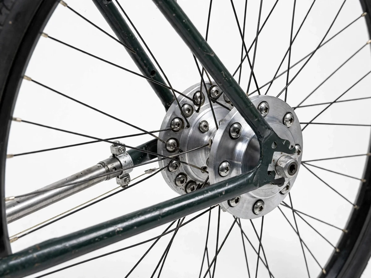
A bicycle chain is efficient but exposed: it stretches, rusts, derails, needs regular lubrication and cleaning, and soils clothing. Shaft drive is the classic mechanical alternative — motorcycles and early bicycles used it long before chains became universal — yet it rarely appears in student workshops because it demands bevel gear geometry, accurate shaft alignment and bearing support in a compact space. This project converts a standard steel-frame bicycle to shaft drive: the chain, chainring and sprocket are removed, a bevel gear pair is fitted at the bottom bracket, a slender shaft runs inside a tube along the right chainstay, and a second bevel pair inside a rear hub housing drives the wheel. The build makes torque transmission, gear ratio selection, backlash setting and drivetrain losses tangible on a rideable machine.
How it works
- The rider pedals the cranks; crank torque enters the bottom-bracket shaft in the usual way.
- The first bevel gear, keyed to the crank axle, meshes with its mating bevel gear and turns the torque through 90 degrees.
- The longitudinal drive shaft, carried on ball bearings inside its tube, transmits that torque along the right side of the frame.
- At the rear, the shaft's bevel gear meshes with the hub bevel gear inside the sealed housing, turning the torque back onto the wheel axis.
- The hub bevel gear drives the rear wheel through the hub shell; the overall ratio is set by the two bevel pairs' tooth counts.
- Shim adjustment at both housings sets gear mesh depth and backlash, trading a little friction for quiet, reliable engagement.
Tech stack:
- Bevel gear pairs (straight-tooth, steel)
- EN8 steel drive shaft with ball-bearing supports
- Machined aluminium gear housings (lathe and milling work)
- Standard 26-inch steel bicycle frame and wheels
- Shim washers and eccentric bearing seat for backlash setting
- CAD drawings for housings and shaft (dimensioned)
| Parameter | Value |
|---|---|
| Base bicycle | 26-inch wheel steel-frame bicycle (standard donor cycle) |
| Drive type | Two bevel gear pairs with an intermediate longitudinal shaft |
| Bevel gear module | Module 2 mm (design target) |
| Tooth counts | Approximately 16 teeth pinion / 32 teeth gear per pair (design target) |
| Overall drive ratio | Approximately 1:1 to 1:2 range depending on selected tooth counts (design target) |
| Drive shaft | Approximately 10 mm diameter EN8 steel (design target) |
| Added weight over chain drive | Approximately 1.5–2.5 kg (expected) |
| Drivetrain efficiency | Approximately 90–95% (expected; lower than a clean, lubricated chain drive) |
| Speeds | Single speed in the base build; 3-speed internal hub optional |
| Top speed | Rider- and ratio-dependent; no fixed figure is claimed |
Project features
- [Bottom-bracket bevel gear pair] A pair of mating bevel gears (module and tooth counts in the specifications) replaces the chainring, turning the crank axis torque through 90 degrees into the longitudinal shaft.
- [Enclosed drive shaft] A steel shaft of approximately 10 mm diameter (design target) runs inside a protective tube along the right chainstay, supported by miniature ball bearings, so the transmission is sealed from dust, water and clothing.
- [Rear hub bevel pair and housing] A second bevel pair inside a machined aluminium housing at the rear dropout turns the shaft torque back into the wheel axis and drives the hub.
- [Backlash and mesh adjustment] Shim washers and an eccentric bearing seat let the builder set bevel gear mesh and backlash during assembly — the key tuning skill this project teaches.
- [Standard frame conversion] The conversion starts from a common 26-inch steel bicycle frame, so brakes, steering and wheels stay standard and serviceable.
- [Optional multi-speed hub gear] A 3-speed internal hub gear can be specified as an optional customization; the base build is single-speed with the ratio fixed by the bevel tooth counts.
- [Rideable demonstration] The finished bicycle is ridden, not just spun on a stand, so steering, pedalling effort and noise can be judged directly in the viva demonstration.
What is included
- Converted rideable chainless bicycle (shaft-drive prototype)
- Machined bevel gear housings, drive shaft and bearing set as fitted
- Dimensioned drawings of the housings, shaft and gear selection
- Assembly and backlash-adjustment guide
- Project report PDF (design calculations, gear ratio working, build log)
- PPT presentation for final review
- Viva Q&A preparation document (bevel gears, torque path, backlash, efficiency trade-offs)
Limitations & prerequisites
- A shaft drive has more sliding contact than a chain, so pedalling losses are higher — approximately 90–95% efficiency is expected, below a clean chain drive.
- Bevel gear mesh is alignment-critical: poor shimming shows up immediately as noise, wear or binding.
- The housings and shaft need lathe and milling access; this is not a bolt-on kit for an arbitrary frame.
- The conversion adds approximately 1.5–2.5 kg (expected) over the donor bicycle's chain drive.
- Gear ratio changes mean changing gear pairs, not swapping a sprocket — ratio changes are workshop jobs.
- The prototype is a student build, not a commercial product; it is not certified for road sale.
Frequently Asked Questions
Why remove the chain at all?
The chain is efficient but exposed to dirt and wear and needs frequent lubrication. A shaft drive is enclosed, clean and low-maintenance, and it demonstrates bevel gears, torque redirection and backlash setting — a richer mechanical design exercise than fitting a standard chain drive.
Is a shaft-drive bicycle less efficient than a chain bicycle?
Yes, honestly: two bevel meshes and shaft bearings lose more energy than a clean chain, and approximately 90–95% efficiency is the expected range here. The project report presents this trade-off with the reasoning, rather than hiding it.
Can the gear ratio be changed?
Yes, by changing the tooth counts of one or both bevel pairs, which changes the overall ratio. Unlike a sprocket swap it is a machining-and-assembly job, and the drawings show how the fitted pairs were selected.
Which parts are machined and which are standard?
The donor bicycle, wheels, brakes and bearings are standard parts. The two gear housings, the drive shaft, its support tube and the bearing seats are machined for this conversion and supplied as dimensioned drawings.
Is this project suitable for a final-year project?
Yes — for Mechanical Engineering programs. It demonstrates power transmission design, bevel gear geometry, shaft and bearing selection, tolerance and backlash control, and honest efficiency analysis on a working, rideable prototype.
Components & software requirements
- Bevel gear pairs (straight-tooth, steel)
- EN8 steel drive shaft with ball-bearing supports
- Machined aluminium gear housings (lathe and milling work)
- Standard 26-inch steel bicycle frame and wheels
- Shim washers and eccentric bearing seat for backlash setting
- CAD drawings for housings and shaft (dimensioned)
Delivery information
Built-to-order project. Delivery timeline is shared after order confirmation based on current queue.
Support terms
Complete documentation, setup guide, and viva preparation included. Support for setup and explanation provided.
Download free synopsis (PDF)
Enter your name and email — the synopsis PDF downloads immediately. We may send occasional project updates; no spam, unsubscribe anytime.