
More project photos (3)
The problem
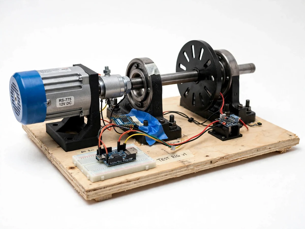
Rolling-element bearings fail quietly and then catastrophically — a spalled race in a pump or gearbox can halt a production line. Industry therefore watches bearings with vibration analysis: each defect type (outer race, inner race, rolling element) produces characteristic frequencies computed from the bearing's geometry and shaft speed. The catch for students is access: real faulted machines are rare, and the analyzers are expensive lab instruments, so the formulas are learned without ever seeing a spectrum. This project closes that gap with a small, safe bench-top rig: a motor spins a shaft through a test bearing with a known seeded defect, a MEMS accelerometer captures the vibration, and a Python tool shows the waveform and FFT with the theoretical fault frequencies overlaid. The student sees the defect they fitted appear as a peak where the formula says it should — the core insight of predictive maintenance, on a classroom budget.
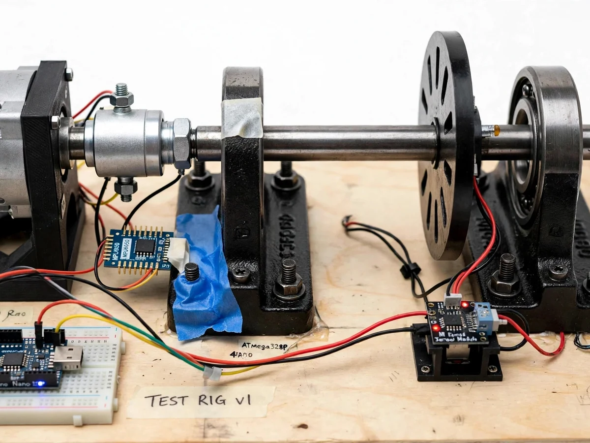
Triaxial MEMS accelerometer mounted on the bearing housing.
Follow the working sequence
How it works
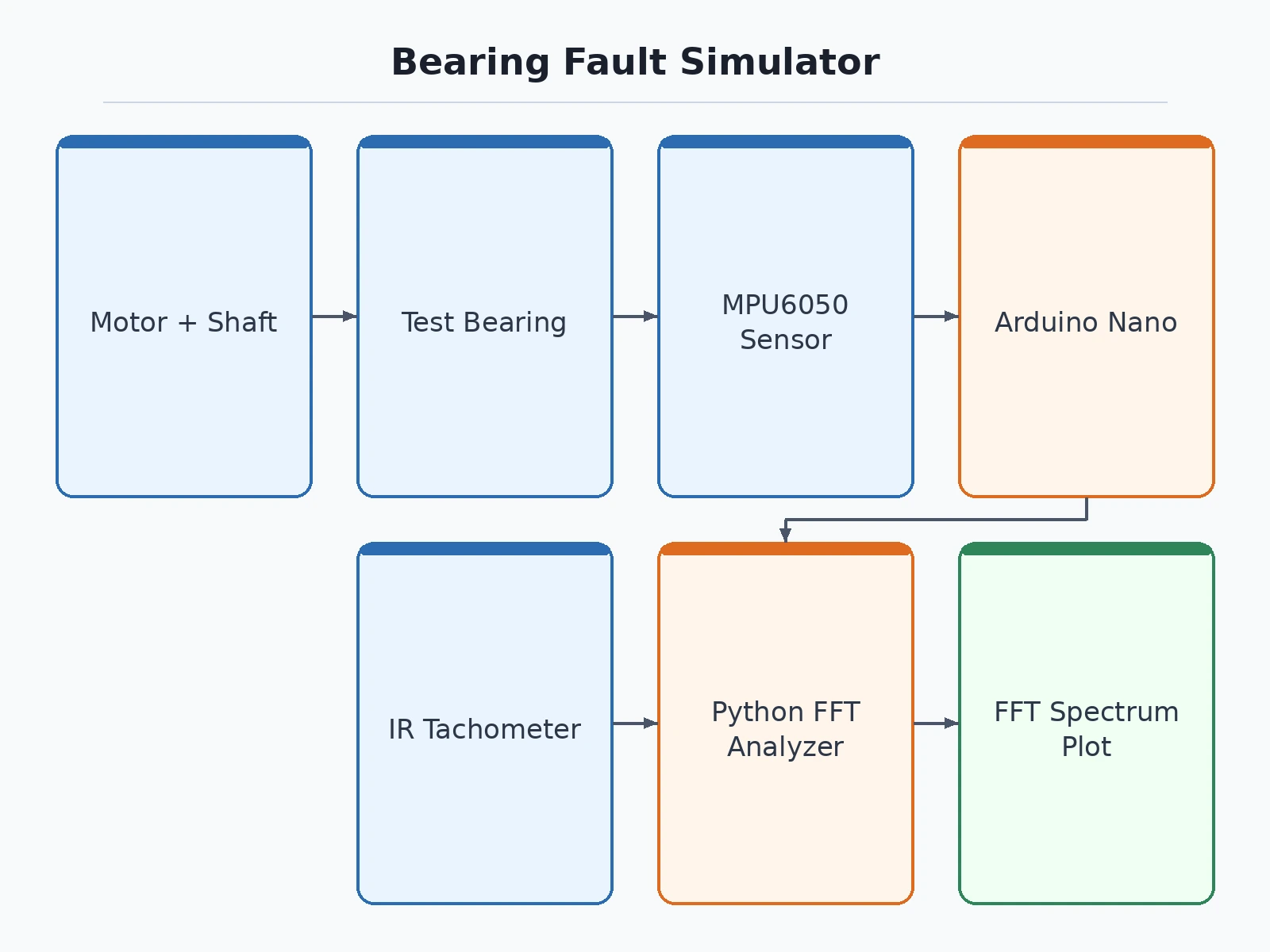
- A test bearing (healthy or one seeded fault) is fitted in the pillow-block housing on the motor-driven shaft.
- The MPU6050 on the housing measures vibration in three axes; the Arduino Nano streams the samples over USB serial.
- The IR tachometer measures shaft RPM, displayed on the 16x2 LCD and attached to each recording.
- The Python analyzer computes the FFT of the acceleration signal and plots waveform, spectrum, RMS and crest factor.
- The fault-frequency calculator derives BPFO, BPFI, BSF and FTF from the entered bearing geometry and measured RPM, drawing markers on the spectrum.
- The student compares the marked peaks against the healthy-bearing baseline to identify the seeded defect's signature.
Tech stack:
- Arduino Nano (ATmega328P), firmware in Arduino IDE
- MPU6050 triaxial MEMS accelerometer (I2C, ±2 g range)
- 775 DC motor with PWM speed control
- 6205 deep-groove ball bearing as the test bearing
- IR tachometer module + 16x2 LCD
- Python analyzer (NumPy FFT, matplotlib)
- Pillow-block bearing rig frame
| Parameter | Value |
|---|---|
| Rig | Bench-top frame; 775 DC motor driving a steel shaft on pillow-block bearings |
| Test bearing | 6205 deep-groove ball bearing (25 × 52 × 15 mm); seeded outer-race, inner-race and ball defects |
| Accelerometer | MPU6050, ±2 g range, 16-bit ADC (MEMS, educational grade) |
| Controller | Arduino Nano (ATmega328P), USB-serial streaming |
| Sampling | Effective streaming rate of a few hundred samples per second — not a lab-grade kHz DAQ |
| Speed sensing | IR tachometer, RPM on LCD and in capture logs |
| Analyzer | Python: time waveform, FFT spectrum, RMS, crest factor, fault-frequency markers |
| Fault frequencies | BPFO, BPFI, BSF, FTF computed from bearing geometry and measured RPM |
Project features
- [Seeded-fault test bearings] 6205 deep-groove ball bearings with machined defects — outer-race groove, inner-race notch and rolling-element flat, one fault per supplied bearing, plus a healthy reference bearing.
- [Triaxial vibration capture] An MPU6050 MEMS accelerometer mounted on the bearing housing streams acceleration data to an Arduino Nano over USB serial.
- [Live waveform and FFT analyzer] A Python tool plots the time waveform, FFT spectrum, RMS level and crest factor as data arrives.
- [Fault-frequency calculator] Enter ball count, ball and pitch diameters, contact angle and shaft RPM; the tool computes BPFO, BPFI, BSF and FTF and overlays markers on the spectrum.
- [Variable-speed testing] PWM motor speed control lets the student verify that fault peaks track shaft RPM as the formulas predict.
- [Healthy-vs-faulty comparison] Overlay spectra from the healthy reference bearing against each faulted bearing to make the defect signature visible.
- [Tachometer readout] An IR sensor measures shaft RPM, shown on the LCD and logged alongside each capture.
What is included
- Assembled bench-top rig (motor, shaft, bearing housings, sensor mount)
- Set of test bearings: healthy reference + three seeded-fault bearings
- Arduino firmware source code
- Python analyzer with fault-frequency calculator
- Wiring diagram and component list
- Bearing-geometry worksheet with the fault-frequency formulas
- Project abstract PDF
- Project report (theory, rig design, methodology, sample spectra)
- PPT presentation and viva Q&A document
Advantages
- Seeded-fault 6205 deep-groove ball bearings: an outer-race groove, an inner-race notch and a rolling-element flat, one fault per supplied bearing, plus a healthy reference bearing.
- Triaxial vibration capture from an MPU6050 accelerometer mounted on the bearing housing, streamed to an Arduino Nano over USB serial, with a live waveform, FFT spectrum, RMS level and crest factor.
- Fault-frequency calculator: enter ball count, ball and pitch diameters, contact angle and shaft RPM, and the tool computes BPFO, BPFI, BSF and FTF and overlays markers on the spectrum.
- Variable-speed PWM motor control lets the student verify that fault peaks track shaft RPM, and healthy-vs-faulty spectrum overlays make each defect signature visible.
- Tachometer readout: an IR sensor measures shaft RPM, shown on the LCD and logged alongside each capture.
Disadvantages
- The Arduino/USB link streams only a few hundred samples per second, so high-frequency fault harmonics alias; this is a demonstrator, not a kHz-class lab DAQ.
- The MPU6050 MEMS noise floor is far above IEPE laboratory accelerometers, so only the coarse seeded faults are resolvable, not incipient real-world defects.
- Seeded defects are machined and deliberately exaggerated, while real fatigue spalls develop and look different.
- The rig's own motor imbalance and frame resonances add a baseline vibration floor that the student must account for.
- This is an academic demonstrator of the method, not ISO 10816-certified condition monitoring equipment.
Limitations & prerequisites
- The Arduino/USB link streams only a few hundred samples per second, so high-frequency fault harmonics alias — this is a demonstrator, not a kHz-class lab DAQ.
- The MPU6050's MEMS noise floor is far above IEPE laboratory accelerometers; only the coarse seeded faults are resolvable, not incipient real-world defects.
- Seeded defects are machined and deliberately exaggerated; real fatigue spalls develop and look different.
- The rig's own motor imbalance and frame resonances add a baseline vibration floor that the student must account for.
- This is an academic demonstrator of the method, not ISO 10816-certified condition monitoring equipment.
Frequently Asked Questions
Is this project suitable for a final-year project?
Yes — for Mechanical and Mechatronics programs, combining machine design, sensor interfacing, signal processing and the theory of predictive maintenance.
Which bearing faults can it demonstrate?
Outer-race, inner-race and rolling-element defects — one seeded fault per supplied test bearing, plus a healthy reference for comparison.
How are the fault frequencies computed?
From the standard geometry formulas: ball count, ball diameter, pitch diameter, contact angle and shaft RPM give BPFO, BPFI, BSF and FTF; the analyzer overlays them on the spectrum.
Can it diagnose a real failing bearing?
The method is the same one industry uses, but the rig's MEMS sensor and sampling rate are educational grade — it demonstrates the technique rather than replacing lab instruments.
What sampling rate does it achieve?
An effective few hundred samples per second over USB serial — enough for the fundamental fault frequencies of the seeded defects, not for high-frequency envelope analysis.
What are the main limitations?
Limited sampling rate, MEMS noise floor, exaggerated machined defects and rig self-vibration — detailed under Limitations. Suitable for B.E./B.Tech final-year projects in Mechanical and Mechatronics.
Components & software requirements
- Arduino Nano (ATmega328P), firmware in Arduino IDE
- MPU6050 triaxial MEMS accelerometer (I2C, ±2 g range)
- 775 DC motor with PWM speed control
- 6205 deep-groove ball bearing as the test bearing
- IR tachometer module + 16x2 LCD
- Python analyzer (NumPy FFT, matplotlib)
- Pillow-block bearing rig frame
Delivery information
Built-to-order project. Delivery timeline is shared after order confirmation based on current queue.
Support terms
Complete documentation, setup guide, and viva preparation included. Support for setup and explanation provided.
Download free synopsis (PDF)
Enter your name and WhatsApp number — the synopsis PDF downloads immediately. We may send occasional project updates on WhatsApp; no spam.