
More project photos (3)


The problem
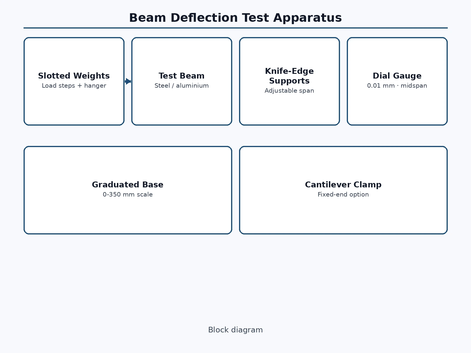
Every mechanical and civil student derives the beam deflection formula, but few ever watch a dial gauge needle move as weights go on a real beam. Bench deflection rigs exist in department labs, yet they are shared, queued and usually demonstrated rather than operated by students. This project builds a student-owned version: a beam on two adjustable knife-edge supports over a graduated base, loaded at midspan (or anywhere) with slotted weights on a hanger, while a 0.01 mm dial gauge on a magnetic stand reads the deflection. The student loads the beam in steps, records deflection, and checks the numbers against the theoretical formula — then changes the span, swaps the beam material, or converts the setup to a cantilever and sees how the theory holds up each time.
How it works
- The beam is laid across the two knife-edge supports at a chosen span, read off the graduated base scale.
- The dial gauge is positioned on its magnetic stand with the plunger touching the beam at midspan, and the dial is zeroed.
- Weights are added to the hanger in equal steps (for example 0.5 kg at a time), and the dial reading is recorded at each step after the needle settles.
- The student plots load against deflection, finds the slope, and compares the measured deflection with the theoretical value from the standard formula using the beam's measured dimensions.
- The span is changed (or the aluminium beam is swapped in) and the test repeated, showing how deflection scales with span cubed and with the material's modulus.
- The cantilever clamp is fitted and the point-load-at-free-end experiment is run, completing the theory-verification set for the report.
Tech stack:
- Graduated machined base
- Adjustable knife-edge supports
- Dial gauge with magnetic stand
- Slotted weight set and hanger
- Mild-steel and aluminium beams
- Cantilever clamp block
- Dimensioned fabrication drawings
- Load-deflection test procedure
| Parameter | Value |
|---|---|
| Base scale | 0–350 mm graduated (design) |
| Dial gauge least count | 0.01 mm per division (design) |
| Weight set | 0.5–5 kg in steps with hanger (design set) |
| Beam section | 25 × 6 mm rectangular, 400 mm long (design) |
| Beam materials | Mild steel and aluminium supplied |
| Support type | Adjustable knife edges + cantilever clamp (design) |
| Footprint | Approximately 450 × 200 mm (expected) |
| Expected deflection range | Approximately 0–10 mm at midspan (design target, student-measured) |
Project features
- [Graduated base] A machined base with a 0–350 mm engraved scale so support positions and load points are set and recorded precisely.
- [Adjustable knife-edge supports] Two supports slide along the base and clamp at any span, giving true simply supported conditions for spans the student chooses.
- [0.01 mm dial gauge] A dial indicator on a magnetic stand reads midspan deflection to one hundredth of a millimetre.
- [Slotted weight set] A calibrated-style set of slotted masses with a hanger, added in steps to build the load–deflection curve.
- [Interchangeable beams] Mild-steel and aluminium beams of the same section are supplied, so the material's effect on deflection is measured, not just claimed.
- [Cantilever conversion] A clamp block converts one support into a fixed end, letting the student run the classic cantilever point-load experiment on the same rig.
- [Fabrication drawings] Dimensioned drawings of the base, supports, hanger and gauge stand for the report's fabrication chapter.
- [Theory comparison sheets] A procedure with load–deflection tables and the formula worksheets the student fills in and compares.
What is included
- Fabricated beam deflection apparatus (base, supports, gauge stand, hanger)
- Dial gauge (0.01 mm) with magnetic stand
- Slotted weight set with hanger
- Mild-steel and aluminium beams
- Cantilever clamp block
- Dimensioned fabrication drawings
- Step-by-step test procedure with load–deflection and theory-comparison sheets
- Project report PDF (background, fabrication, test methodology, results format)
- PPT presentation for final review
- Viva Q&A preparation document (deflection formula, support conditions, modulus comparison)
Limitations & prerequisites
- A teaching rig — deflections are student-measured with a manual dial gauge, with typical reading uncertainty around ±0.02 mm.
- The beam's own weight is small but not zero; the procedure notes it as a documented approximation rather than a hidden error.
- Knife edges approximate ideal simple supports; slight seating differences between runs are part of what the student discusses in the error analysis.
- Weights are a student-scale set — loads stay within the beam's elastic range by design, which is also the point of the experiment.
- No measured accuracy is claimed for the rig; agreement with theory is the student's own finding from their own readings.
Frequently Asked Questions
What is the experiment actually proving?
That the textbook deflection formula predicts what really happens: load the beam, measure the sag with the dial gauge, and check the number against the formula. Then change the span or material and watch the prediction change too.
Why does the span matter so much?
Deflection grows with the cube of the span — doubling the span makes the sag roughly eight times larger. The rig's sliding supports let students verify this dramatic relationship in one sitting.
How is the dial gauge reading taken?
The magnetic stand holds the gauge with its plunger touching the beam; the student zeroes the dial, adds each weight, waits for the needle to settle and records the reading. The procedure covers parallax-free reading.
What does the cantilever setup add?
A second classic experiment on the same hardware: clamp one end, load the free end, and verify the cantilever deflection formula — two theory checks for one build.
Can I test a beam of my own material?
Yes, if it matches the support geometry and stays within the elastic load range; the worksheet accepts any measured dimensions and modulus the student enters.
Is this project suitable for a final-year project?
Yes — for Mechanical Engineering programs. It combines fabrication, experimental method, and theory verification, and the report is built on the student's own measured load–deflection data. Suitable for B.E./B.Tech final-year projects in Mechanical Engineering.
Components & software requirements
- Graduated machined base
- Adjustable knife-edge supports
- Dial gauge with magnetic stand
- Slotted weight set and hanger
- Mild-steel and aluminium beams
- Cantilever clamp block
- Dimensioned fabrication drawings
- Load-deflection test procedure
Delivery information
Built-to-order project. Delivery timeline is shared after order confirmation based on current queue.
Support terms
Complete documentation, setup guide, and viva preparation included. Support for setup and explanation provided.
Download free synopsis (PDF)
Enter your name and WhatsApp number — the synopsis PDF downloads immediately. We may send occasional project updates on WhatsApp; no spam.