
More project photos (3)

The problem
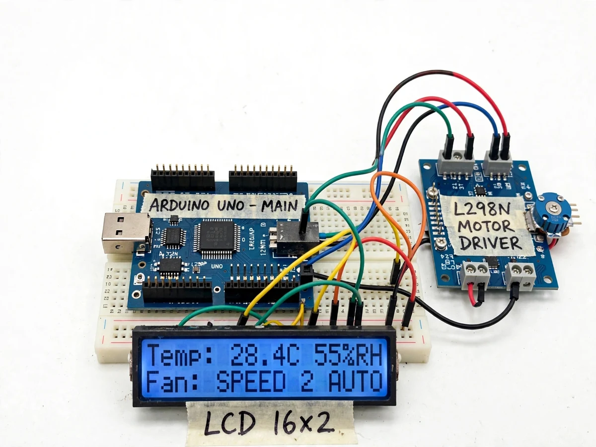
A fan left on full speed in a cool room wastes power and is uncomfortable; one on low in a hot humid room does nothing. People adjust fans by feel, which means the setting is wrong most of the day. Temperature and humidity sensors can make that decision continuously and better than a guess. This project builds a student-scale automatic fan speed controller on an Arduino: a DHT22 sensor reports temperature and humidity, the firmware maps temperature bands to four PWM speed levels with a humidity boost, an L298N driver runs a DC fan at the selected speed, and the LCD shows all three values live.
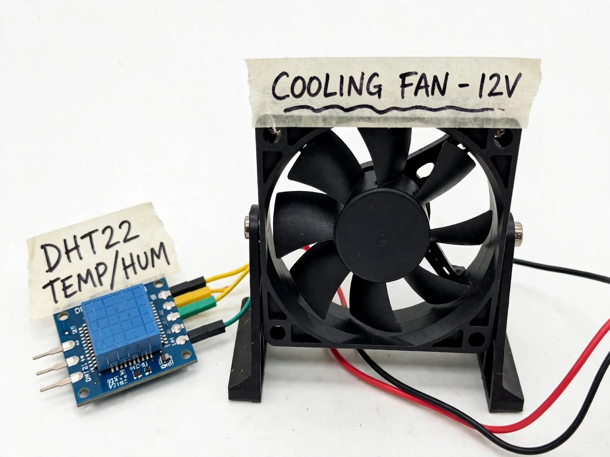
Digital temperature-humidity sensor reporting both values over a single wire.
Follow the working sequence
How it works
- The DHT22 sensor reports temperature and humidity to the Arduino every couple of seconds; both appear on the LCD.
- Firmware compares the temperature against four bands and selects the matching PWM speed level.
- If humidity crosses the high-humidity mark, the logic boosts the selected level by one step for comfort.
- Hysteresis at each band edge means the temperature must move decisively before the speed changes, preventing oscillation.
- The Arduino outputs the PWM duty cycle through the L298N driver, and the DC fan runs at the selected speed.
- The manual buttons switch to manual mode and set any level directly; the mode button returns control to the automatic loop.
Tech stack:
- Arduino Uno (ATmega328P)
- DHT22 temperature-humidity sensor
- DC fan with L298N driver (PWM)
- 16x2 character LCD
- Push buttons
- Arduino IDE (C/C++ firmware)
- 12 V fan supply + 5 V logic
| Parameter | Value |
|---|---|
| Controller | Arduino Uno (ATmega328P) |
| Sensing | DHT22, temperature ±0.5 °C / humidity ±2% RH per datasheet |
| Speed levels | 4 PWM levels + humidity boost (design) |
| Motor drive | L298N, PWM speed control |
| Display | 16x2 LCD (temp, humidity, speed) |
| Override | Manual up/down + auto/manual mode buttons |
| Power | 12 V fan supply + 5 V logic (design) |
Project features
- [Temperature-band speed control] Four PWM speed levels map to temperature bands, so the fan speeds up as the room warms and slows as it cools.
- [Humidity boost] High humidity readings add a speed boost within the firmware logic, addressing muggy conditions temperature alone misses.
- [DHT22 sensing] A digital temperature-humidity sensor reports both values over a single wire with the sensor's datasheet accuracy.
- [Live LCD display] A 16x2 LCD shows temperature, humidity and the current fan speed level continuously.
- [Manual override buttons] Up/down buttons set the speed manually at any time; auto mode resumes with a mode button.
- [PWM motor driving] An L298N driver runs the DC fan with smooth PWM speed control from the Arduino.
- [Hysteresis between bands] Band edges use hysteresis so the fan doesn't oscillate between speeds at a boundary temperature.
What is included
- Working model fan setup with DHT22 sensor, Arduino, L298N driver and LCD
- Complete firmware with commented band-mapping and PWM logic
- Temperature-band configuration guide
- Wiring diagram and connection table
- Project report PDF (background, system design, firmware logic, comfort-control analysis)
- PPT presentation for final review
- Viva Q&A preparation document (DHT22, PWM, L298N, Arduino)
Limitations & prerequisites
- Temperature and humidity accuracy follow the DHT22 datasheet (±0.5 °C, ±2% RH); no independent calibration measurement is claimed.
- The demo uses a DC fan with PWM — a real AC ceiling fan needs a different (triac/phase-control) drive, which is outside this build's scope.
- Comfort is subjective; the temperature bands are design defaults the buyer tunes to their own preference.
- The DHT22 samples every couple of seconds by design, so very rapid temperature swings are smoothed.
- Sensor placement matters — mounting the DHT22 in the fan's own airflow skews readings, noted in the setup guide.
- No Wi-Fi remote control is included — operation is fully on-device.
Frequently Asked Questions
How does it decide the fan speed?
Temperature bands map to four PWM levels — warmer rooms get higher speeds. High humidity adds a one-step boost, and hysteresis at band edges stops the speed from flickering at boundaries.
Can I set the speed myself?
Yes — the up/down buttons switch to manual mode and set any level directly, and the mode button hands control back to the automatic loop.
Why a DC fan and not a ceiling fan?
A DC fan allows clean PWM speed control for a student demo. Driving an AC ceiling fan needs phase-control electronics, which the report lists as a possible extension.
How accurate are the readings?
The project uses the DHT22 datasheet figures (±0.5 °C, ±2% RH) and claims nothing better — the report is explicit about this.
Will the fan keep changing speed annoyingly?
Hysteresis at each band edge means the temperature has to move decisively before the level changes, so boundary hovering doesn't cause oscillation.
Is this project suitable for a final-year project?
Yes — for Electronics, Electrical and IoT & Embedded programs. It covers digital sensor interfacing, PWM motor control, band-mapping logic and a genuinely useful automation. Suitable for B.E./B.Tech final-year projects in Electronics, Electrical and IoT & Embedded.
Components & software requirements
- Arduino Uno (ATmega328P)
- DHT22 temperature-humidity sensor
- DC fan with L298N driver (PWM)
- 16x2 character LCD
- Push buttons
- Arduino IDE (C/C++ firmware)
- 12 V fan supply + 5 V logic
Delivery information
Built-to-order project. Delivery timeline is shared after order confirmation based on current queue.
Support terms
Complete documentation, setup guide, and viva preparation included. Support for setup and explanation provided.
Download free synopsis (PDF)
Enter your name and WhatsApp number — the synopsis PDF downloads immediately. We may send occasional project updates on WhatsApp; no spam.