
More project photos (2)
The problem
Road accidents frequently come down to one factor: the gap between a driver seeing an obstacle and the brakes engaging. At city speeds, a half-second delay in reaction covers several metres — enough to turn a near miss into a collision. Automatic emergency braking closes that gap by letting the vehicle decide and act on its own, but the technology is hard to grasp from diagrams alone, since it couples sensing, control logic, and forceful actuation. Students of mechanical and automation engineering need a physical system where they can see the full loop — obstacle detected, decision made, actuator fired — and measure the timing between them. Pneumatics is the natural actuator choice: compressed air delivers fast, powerful, repeatable force, which is why real trucks and buses use air brakes. A model-scale rig makes this industrial principle bench-accessible, letting students tune thresholds, measure response times, and test fail-safe behaviour directly.
How it works
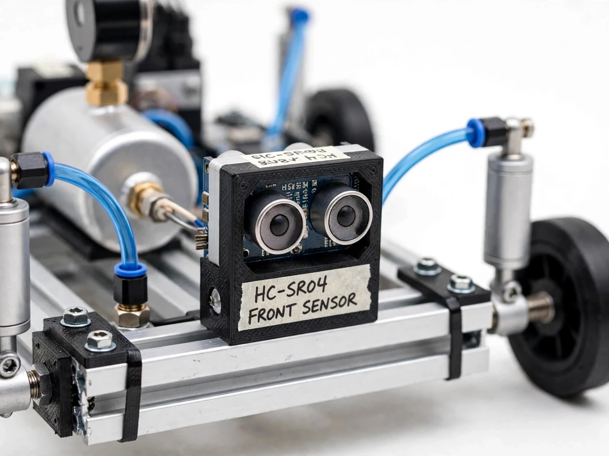
- The ultrasonic sensor on the chassis nose continuously measures the distance to obstacles ahead.
- The Arduino reads the distance and compares it against the set braking threshold (adjustable via onboard potentiometer/buttons).
- When the distance drops below the threshold, the controller energizes the 5/2 solenoid valve.
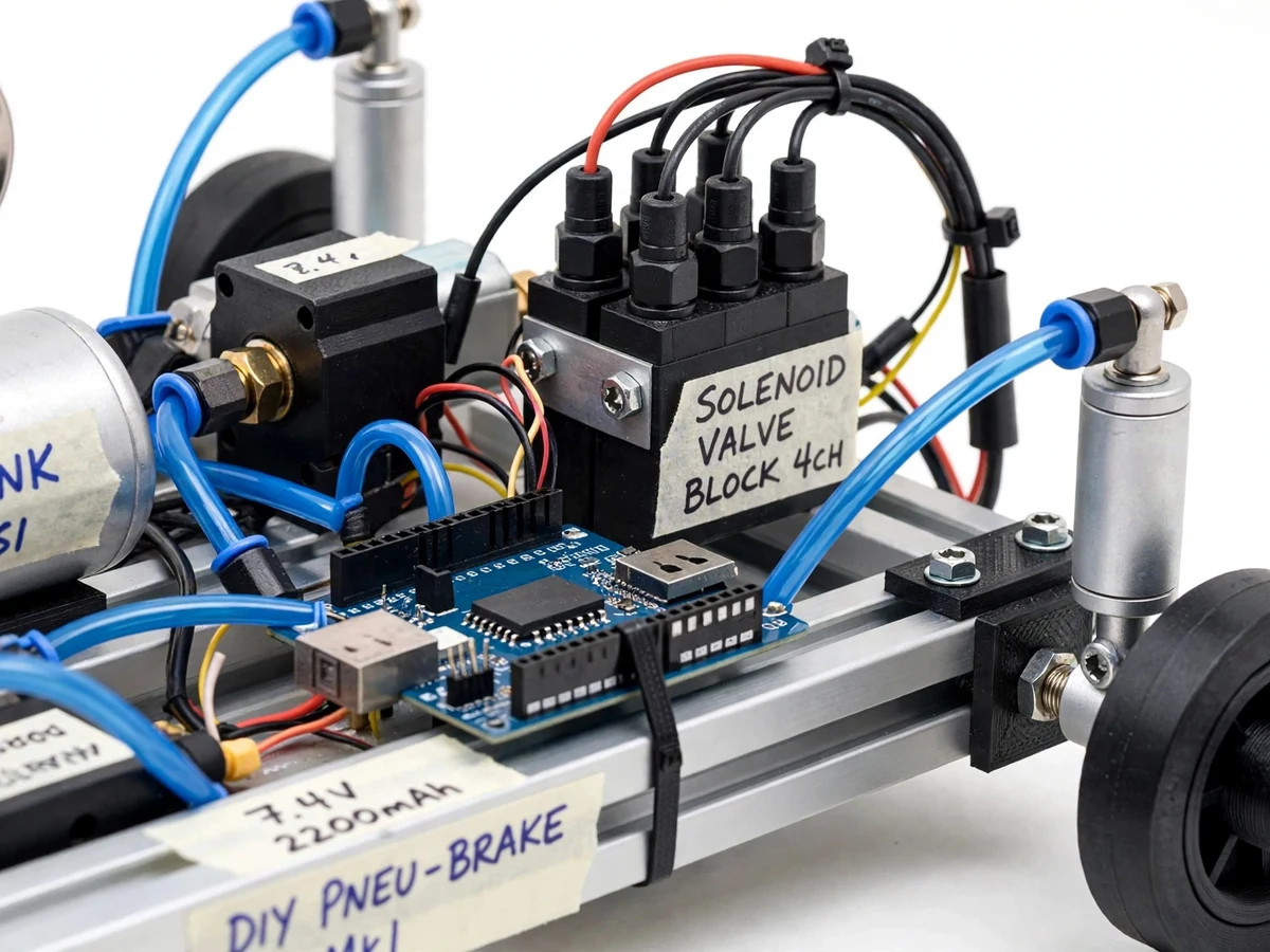
- Compressed air from the tank flows through the valve into the double-acting pneumatic cylinders.
- The cylinder pistons extend and actuate the brake linkage, clamping the wheels to a stop.
- A buzzer and red LED signal the braking event; a green LED shows normal monitoring.
- Once the obstacle clears, the valve de-energizes, air exhausts, the cylinders retract, and the brakes release.
Project features
- Ultrasonic obstacle detection (HC-SR04) with adjustable trigger distance
- Automatic brake actuation via 5/2 solenoid valve and pneumatic cylinders
- Complete sense–decide–actuate loop running on an Arduino controller
- Manual override switch for driver take-over at any moment
- Status LEDs and buzzer indicating monitoring, warning and braking states
- Mini air tank with pressure gauge and regulator for consistent braking force
- Response-time measurement: sensor trigger to full brake engagement, logged per run
- Fail-safe design: brakes release when power or air is removed
- Rolling chassis model with wheels — a moving demonstration of the full loop
What is included
- Working rolling-chassis prototype with wheels and brake linkage
- Pneumatic circuit: cylinders, solenoid valve, air tank, gauge, tubing
- Arduino control firmware with adjustable threshold logic
- Pneumatic circuit diagram + electrical wiring diagram
- Project report PDF (theory, circuit design, response-time test procedure, conclusion)
- PPT presentation
- Viva Q&A preparation document (pneumatics, Pascal's law, solenoid operation, safety)
FAQs
- How is this different from ABS in cars? ABS modulates brake pressure during driver-initiated braking to prevent wheel lock-up. This build is automatic emergency braking: it detects the obstacle and applies the brakes itself, with no driver input. The two are complementary safety systems.
- What air pressure does the system need? The rig runs at 4–6 bar from a mini air tank with a regulator and gauge. Braking force scales with pressure, so the regulator keeps it consistent across runs.
- What happens if the air or power fails? The solenoid valve falls back to its rest position and the cylinders retract — braking releases and the chassis returns to manual control. This fail-safe behaviour is part of the design.
- Can the braking distance be adjusted? Yes. The trigger threshold is set in the Arduino firmware and adjustable on the model, so different braking distances can be demonstrated during a review.
- Why pneumatics instead of electric actuation? Compressed air delivers fast, powerful, repeatable linear force from compact cylinders — the same reason real trucks and buses use air brakes — and the circuit (tank, valve, cylinders) is simple to build and instrument.
Limitations & prerequisites
- Model-scale demonstration: it proves the control principle, not full-size vehicle braking forces.
- Requires a charged air tank / running compressor — braking force drops as pressure falls.
- Ultrasonic sensing can false-trigger on very close non-hazard objects; the threshold must be tuned.
- No speed-proportional braking (no ABS logic) — it is a binary stop/no-stop actuation.
Components & software requirements
- Arduino UNO (control logic: sensing, thresholding, valve actuation)
- HC-SR04 ultrasonic sensor (obstacle ranging)
- 5/2-way solenoid valve (air routing to cylinders)
- Double-acting pneumatic cylinders (brake actuation)
- Mini air compressor / air tank with pressure gauge and regulator
- 12 V battery pack, status LEDs, buzzer, manual override switch
Specifications
| Parameter | Value |
|---|---|
| Sensing | HC-SR04 ultrasonic, 2 cm – 400 cm range |
| Braking trigger distance | Adjustable, typically 30–100 cm (set at build) |
| Pneumatics | 5/2 solenoid valve, double-acting cylinders |
| Operating air pressure | 4–6 bar (regulated), with pressure gauge |
| Control loop | Arduino: sense → decide → actuate |
| Response time | Sensor trigger to brake engagement, measured per run |
| Braking action | Cylinder-driven brake linkage on chassis wheels |
| Override | Manual switch bypasses automation |
| Indication | Green (monitoring) / red + buzzer (braking) |
| Power | 12 V DC battery pack for controller and valve |