
More project photos (2)
The problem
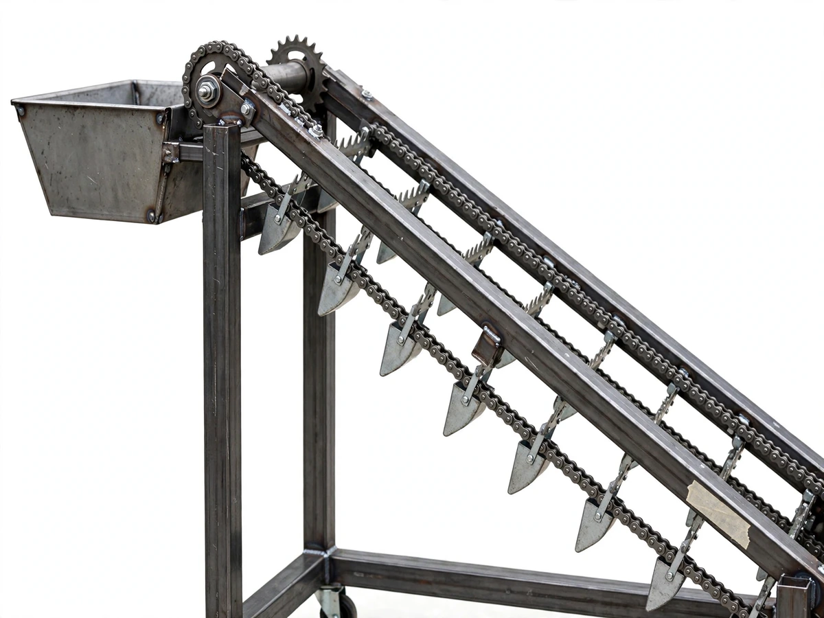
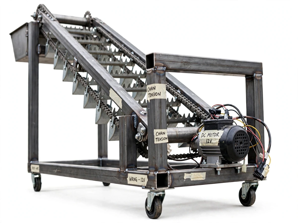
Open drains in cities choke on plastic bottles, carry bags, leaves and food waste, and clearing them still depends on sanitation workers reaching in with rakes and bare hands — slow work that exposes them to infection and toxic gas. Municipal bodies and campus estates need a mechanized collector that lifts floating and sunken waste out of an open drain channel without a worker stepping into it. This project builds exactly that: a trolley-mounted chain-and-sprocket conveyor whose lifter teeth and buckets dip into the drain water, scoop up floating debris and sludge-bound waste, and carry it up an inclined frame into a collection bin at the top. A DC geared motor drives the chain, the whole rig is pushed along the drain on caster wheels, and the frame depth adjusts to suit shallow or deep channels. The result is a working demonstration of chain-drive transmission, load-torque estimation and fabrication practice — the core mechanical-engineering skills the viva will test.
Wheels the machine to the drain edge, lowers the conveyor and sets the chain speed.
Follow the working sequence
How it works
- The machine is wheeled to the drain edge and the conveyor end is lowered into the channel; the frame depth is adjusted so the lifter teeth submerge below the water line.
- The 12 V DC geared motor drives the main sprocket shaft through a reduction stage, moving the roller chain at a slow, constant design-target speed of about 0.15 m/s.
- Lifter teeth snag floating waste (bottles, plastic, leaves) while the perforated buckets scoop sunken and sludge-bound debris as they pass along the drain bed.
- The inclined run carries the collected waste upward; drain-back perforations let water fall back into the channel before it reaches the top.
- At the top sprocket the buckets tip and dump their load into the removable collection tray; the chain returns along the underside for the next pass.
- The debris screen at the intake blocks oversized objects from jamming the chain; the operator clears it between passes along the drain.
- After the run, the tray is lifted out and emptied into a municipal bin, and the operator checks chain tension and sprocket alignment before the next session.
Tech stack:
- MS square-tube frame (welded fabrication)
- Roller chain + matched sprockets (chain-drive transmission)
- 12 V DC geared motor with PWM speed controller
- Sheet-metal lifter teeth, buckets and collection tray
- Swivel caster wheels (manual trolley mobility)
- Arc welding, drilling and grinding (workshop processes)
- CAD fabrication drawings (frame, conveyor, tray)
- Torque and load estimation (mechanical design calculations)
| Parameter | Value |
|---|---|
| Frame | Welded MS square tube, 25 × 25 mm (approximate) |
| Conveyor drive | 12 V DC geared motor, approximately 60 W (design target) |
| Chain speed | Approximately 0.15 m/s at the conveyor run (design target) |
| Lifter buckets | 8–10 perforated sheet-metal buckets, approximately 0.8 L each (design target) |
| Collection tray | Removable tray, approximately 25 L capacity (design target) |
| Adjustable working depth | 300–600 mm below the base frame (design target) |
| Mobility | 4 swivel caster wheels, manual push (approximate) |
| Overall footprint | Approximately 1.5 m × 0.6 m × 1.1 m (L × W × H, approximate) |
| Power source | 12 V battery or 12 V mains adapter, buyer-supplied (approximate) |
| Chain and sprockets | Standard roller chain with matched drive and idler sprockets (approximate) |
Project features
- [Chain-and-sprocket conveyor] A continuous roller chain runs over drive and idler sprockets on an inclined frame, carrying lifter teeth and sheet-metal buckets that dip into the drain water and scoop floating and sunken waste.
- [Collection bin] A removable sheet-metal tray at the top discharge end catches everything the buckets tip out, and can be lifted off for emptying into a municipal bin.
- [DC geared motor drive] A 12 V DC geared motor drives the main sprocket shaft at slow, high-torque speed; a simple PWM speed controller lets the operator adjust chain speed to the waste load.
- [Adjustable frame depth] Slot mounts let the conveyor frame slide down 300–600 mm below the base so the teeth submerge in shallow roadside drains and deeper channels alike.
- [Manual push trolley wheels] Four swivel caster wheels under the base frame let one operator roll the machine along the drain edge and position it for each pass.
- [Debris intake screen] A screen at the conveyor intake stops oversized objects (branches, rags, large rubble) from entering and jamming the chain; the operator clears it between passes.
- [Drain-back buckets] Perforated bucket bottoms let drain water fall back into the channel as waste is carried up, so the bin collects waste rather than litres of water.
- [Chain guard] Sheet-metal guards cover the drive chain and sprockets to keep hands, clothes and the masking-tape labels of a working prototype clear of moving parts.
What is included
- Complete fabrication drawings (frame, inclined conveyor, collection tray, chain guard) in printable CAD format
- Full parts list with standard sizes and approximate sourcing notes
- Motor wiring diagram and speed-controller connection guide
- Step-by-step assembly and alignment procedure (chain tensioning, sprocket alignment)
- Load-test procedure for the buyer to run in their own test drain
- Project report PDF (background, literature survey, design calculations, fabrication methodology)
- PPT presentation for final review
- Viva Q&A preparation document (chain drives, gear ratios, torque, fabrication processes)
Limitations & prerequisites
- Open drains only: the machine is designed for open storm drains and channels — it cannot enter or clean pressurized underground sewer pipes.
- Waste-type limits: it handles floating plastic, leaves, light debris and loose sludge; compacted silt beds and large tree roots are beyond its scope.
- No hazardous materials: never run with chemical effluent or medical waste — the prototype is unlined mild steel, not chemical-grade equipment.
- Demonstration scale: this is a student prototype, not municipal machinery — clearing throughput is a design target, measured by the buyer in their own load tests (procedure supplied).
- No measured throughput claimed: this page claims no measured cleaning rate; the report records the figures the buyer obtains during their calibration runs.
- Safety: wear gloves and work in ventilated areas around open drains; keep hands and clothing clear of the moving chain even with the guards fitted.
Frequently Asked Questions
Can it clean underground sewer pipes?
No. It is built for open drains and channels — the conveyor must dip into an open channel. Pressurized underground pipes are a different class of machine entirely and out of scope.
How much waste can it lift?
The design targets are a 25 L tray, 8–10 buckets of ~0.8 L each and ~0.15 m/s chain speed. Actual collected waste per pass is measured by the buyer in their test drain with the supplied load-test procedure, and those figures go into the report.
Does it run on mains power or a battery?
Either — it needs a 12 V source, which can be a lead-acid battery for field use or a 12 V mains adapter. The power source is buyer-supplied; the wiring diagram covers both.
Why are the chain and sprockets important for the viva?
Because the whole machine is a chain-drive transmission problem: gear ratios, chain pitch, tensioning and alignment, and estimating the motor torque needed for the loaded buckets. Examiners can ask theory on every one of these, and the Q&A kit covers them.
What maintenance does the prototype need?
Chain tension and sprocket alignment checked before each run, light oiling of the chain, and emptying the tray between passes. The alignment procedure is in the included documents.
Is this project suitable for a final-year project?
Yes — for Mechanical, manufacturing and industrial engineering programs. It demonstrates chain-drive design, torque estimation, welding and sheet-metal fabrication, and a socially relevant problem statement. Suitable for B.E./B.Tech final-year projects in Mechanical Engineering.
Components & software requirements
- MS square-tube frame (welded fabrication)
- Roller chain + matched sprockets (chain-drive transmission)
- 12 V DC geared motor with PWM speed controller
- Sheet-metal lifter teeth, buckets and collection tray
- Swivel caster wheels (manual trolley mobility)
- Arc welding, drilling and grinding (workshop processes)
- CAD fabrication drawings (frame, conveyor, tray)
- Torque and load estimation (mechanical design calculations)
Delivery information
Built-to-order project. Delivery timeline is shared after order confirmation based on current queue.
Support terms
Complete documentation, setup guide, and viva preparation included. Support for setup and explanation provided.
Download free synopsis (PDF)
Enter your name and email — the synopsis PDF downloads immediately. We may send occasional project updates; no spam, unsubscribe anytime.