
More project photos (3)
The problem
The 4S Li-Ion Battery Management System with Passive Cell Balancing and Protection is a student-built electrical prototype that answers a practical question: what actually keeps a multi-cell lithium pack safe? A single 18650 cell is 3.7 V nominal (datasheet), but wiring four in series creates a 14.8 V pack whose cells are never perfectly matched — charging the string without supervision lets one cell drift into overcharge while the others lag, and that imbalance is exactly how lithium packs fail dangerously. This project builds a working four-cell pack around a 4S BMS protection board that monitors every cell individually: passive balancing bleeds charge through resistors from the highest cells so the string stays equalized, while protection MOSFETs disconnect the pack on overcharge, over-discharge, overcurrent or short circuit. A small display shows each cell's live voltage, so the balancing behaviour and the protection cutoffs are visible during real charge and discharge cycles. Throughout, the build follows disciplined lithium handling — proper charger, supervised charging, no damaged cells.
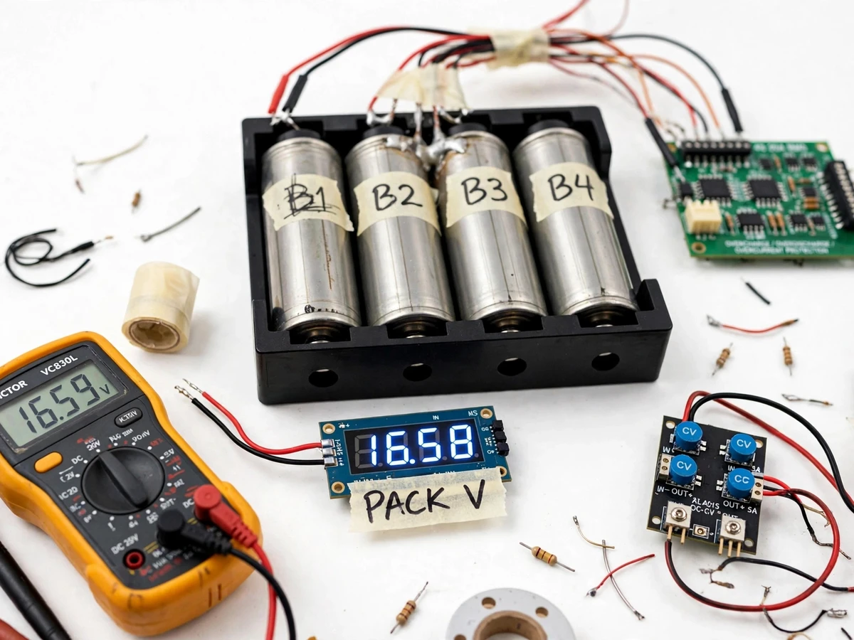
Four 18650 cells in series: 14.8 V nominal, 16.8 V at full charge.
Follow the working sequence
How it works
- Four 18650 cells sit in a 4-cell holder wired in series — 3.7 V nominal each (datasheet), giving a 14.8 V pack that reaches 16.8 V at full charge (4 × 4.20 V, datasheet).
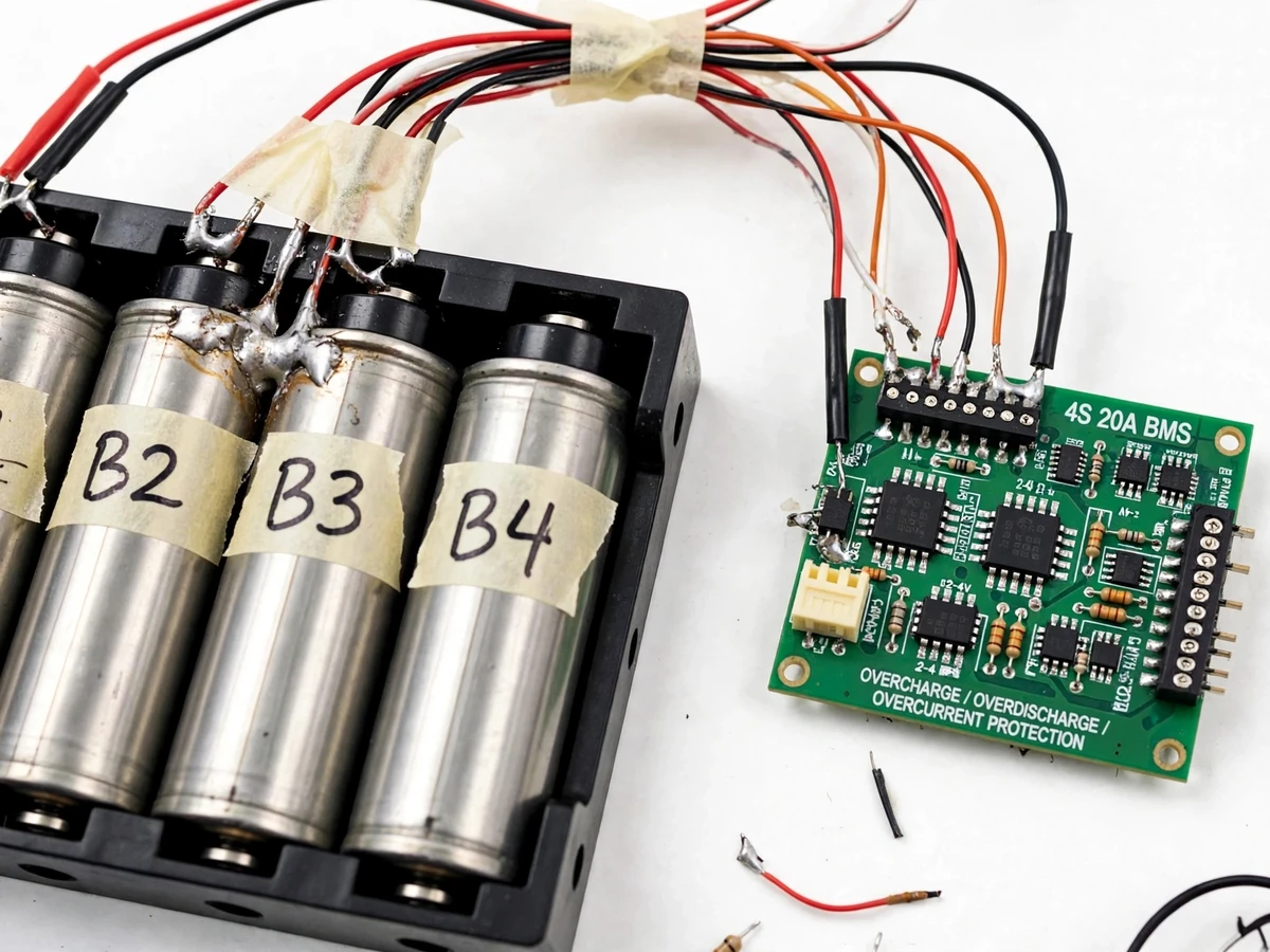
- Balance leads tap every cell junction (B−, B1, B2, B3, B+) into the 4S BMS board, so the board sees each cell's individual voltage rather than just the pack total.
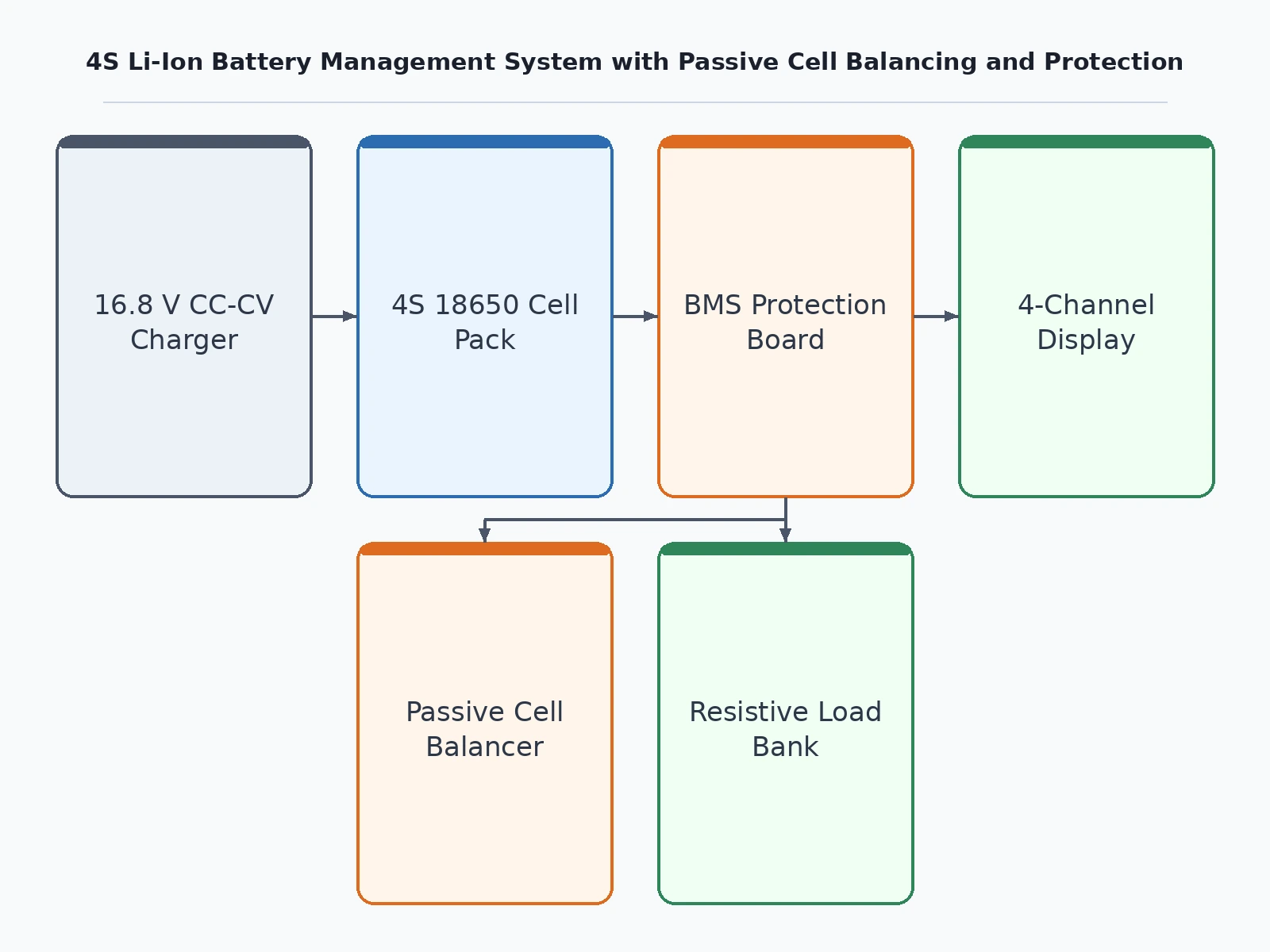
- Charging begins from a proper 16.8 V CC-CV Li-ion charger. The board watches each cell; when any cell rises above the others, passive balancing bleeds it down through the on-board bleed resistors so the string equalizes.
- The 4-channel voltage display shows each cell's live voltage, letting you watch the equalization happen — the highest cell visibly converging with the rest.
- If a cell reaches the overcharge threshold (approximately 4.25–4.30 V per cell, typical for this board class — exact value from the board datasheet), the charge MOSFET opens and charging stops.
- On the discharge side, the resistive load bank draws from the pack terminals. If any cell falls to the over-discharge threshold (approximately 2.5–2.8 V per cell, typical — exact value from the board datasheet), the discharge MOSFET opens and the load is cut; overcurrent or a short circuit trips the same protection path.
- The student then runs the supplied verification procedure: charge the pack, log per-cell voltages at intervals, confirm equalization, and confirm cutoff behaviour with a multimeter — producing measured readings for the report.
Tech stack:
- 4S Li-ion BMS protection board
- 18650 Li-ion cells with 4-cell holder
- 16.8 V CC-CV Li-ion charger
- Resistive DC load bank
- 4-channel digital voltage display
- Multimeter and wiring hand tools
- Balance-lead wiring harness
- Heat-shrink and insulation hardware
| Parameter | Value |
|---|---|
| Pack configuration | 4S1P — four 18650 cells in series |
| Nominal voltage | 14.8 V (4 × 3.7 V, datasheet) |
| Full-charge voltage | 16.8 V (4 × 4.20 V, datasheet) |
| Cell capacity | Cell-dependent — stated from the supplied cells' datasheet, not assumed |
| Overcharge cutoff | Approximately 4.25–4.30 V per cell (typical for this board class; exact value from the board datasheet in the report) |
| Over-discharge cutoff | Approximately 2.5–2.8 V per cell (typical; exact value from the board datasheet) |
| Overcurrent / short-circuit | Board-rating dependent — per the BMS datasheet |
| Balancing | Passive bleed-resistor; balance current board-dependent (approximate, stated in report) |
| Charger | 16.8 V CC-CV Li-ion charger (mandatory — generic adapters are not permitted) |
| Display | 4-channel per-cell voltage readout |
| Runtime on load | Cell-capacity and load dependent — no fixed runtime claimed |
| Build type | Supervised lab prototype — not a certified battery pack |
Project features
- [4S BMS protection board] The heart of the build — monitors each of the four cells through balance leads and drives protection MOSFETs that disconnect the pack on overcharge, over-discharge, overcurrent or short circuit. Thresholds are taken from the supplied board's datasheet and verified by the student with the included test procedure.
- [Passive cell balancing] During charging, the board shunts excess charge from the highest-voltage cells through on-board bleed resistors so the string equalizes instead of drifting apart. The balancing behaviour is visible live on the display — this is the phenomenon the project exists to demonstrate.
- [Per-cell live voltage display] A 4-channel display module shows every cell's voltage continuously, so balancing drift, equalization and protection trips are all observable in real time. The module's low-voltage warning threshold is configurable through its setting buttons.
- [Charger input and load output terminals] A 16.8 V CC-CV Li-ion charger input for safe charging and load output terminals for discharge tests with the supplied resistive load bank — the full charge–discharge cycle is demonstrable on the bench.
- [Lithium-safety build practice] Insulated 4-cell holder, polarity-marked and heat-shrunk leads, fused wiring practice, and a strict handling ruleset: proper charger only, charging always supervised, damaged or swollen cells never used.
- [Buyer-run verification procedure] A step-by-step procedure to verify balance behaviour and protection cutoffs on your own build using the display and a multimeter — every reading in the report is measured by the student, never claimed.
- [Cell-voltage data logging] Optional customization, not in the base build: an Arduino-based logger can be added to record per-cell voltages over a full charge cycle for plotted equalization curves. Quoted separately on request.
What is included
- Assembled 4S 18650 pack with the BMS board wired, labelled and insulated
- 16.8 V CC-CV Li-ion charger and resistive discharge load rig
- 4-channel per-cell voltage display module, wired in
- Wiring diagram and component list with datasheet references
- Buyer-run verification and calibration procedure
- Project report PDF (BMS theory, lithium safety, build log, measured readings)
- PPT presentation for final review
- Viva Q&A preparation document (series strings, balancing, protection circuits, lithium safety)
Limitations & prerequisites
- Li-ion cells demand respect: this is an educational, supervised lab prototype — NOT a certified or commercial battery pack. Never charge unattended, and damaged, swollen or overheated cells must never be used.
- Only the supplied 16.8 V CC-CV Li-ion charger may be used — generic DC adapters have no proper charge profile and risk overcharge; they are banned from the test rig.
- Passive balancing current is small and board-dependent (tens-of-mA class, approximate) — badly mismatched cells equalize slowly, and the procedure documents the expected behaviour honestly.
- Protection thresholds are board-datasheet values, not certified guarantees — the student verifies actual trip points with the multimeter procedure and reports measured values.
- Runtime on load depends on the supplied cells' mAh rating and the load current — no fixed runtime is claimed anywhere.
- The prototype must be stored and handled as a lithium pack: insulated terminals, no metal tools across cells, and charging only on a fire-safe surface under supervision.
Frequently Asked Questions
Which BMS board is used and what does it protect against?
A 4S Li-ion protection board monitors each cell through balance leads and drives MOSFETs that disconnect the pack on overcharge, over-discharge, overcurrent and short circuit, while passively balancing the cells during charge. Typical thresholds for this board class are approximately 4.25–4.30 V per cell on overcharge and 2.5–2.8 V per cell on over-discharge; exact values come from the board's datasheet and are verified with the included test procedure.
Is it safe to charge lithium cells for this project?
Yes, with strict discipline — and that discipline is part of what the project teaches. Charging uses only the supplied 16.8 V CC-CV Li-ion charger, never a generic adapter; charging is always supervised and never left unattended; and damaged, swollen or overheated cells are never used. The prototype is an educational lab demo, not a certified battery pack, and the report documents the full handling ruleset for the viva.
Can I actually see the balancing working?
Yes — that is the point of the display module. Each cell's live voltage is shown during charging, so you can watch the highest cells get bled down while the rest catch up. The included procedure has you log per-cell readings at set intervals, so the report contains your own measured equalization curve rather than a claimed result.
What charger is needed, and can I use any DC adapter?
No — only a proper 16.8 V CC-CV Li-ion charger, which is supplied with the build. A generic DC adapter has no constant-current/constant-voltage profile and no charge termination, so it can push cells into overcharge. Using the wrong charger voids the safety assumptions of the whole build, which is why the correct charger is part of the deliverable.
What are the main limitations of the prototype?
Passive balancing current is small and board-dependent (tens-of-mA class, approximate), so badly mismatched cells equalize slowly. Protection thresholds are board-datasheet values the student verifies by measurement — they are not certified guarantees. Runtime is cell-capacity dependent and no fixed runtime is claimed. The unit is a supervised lab prototype, not a certified pack, and must never power unattended applications.
Is this project suitable for a final-year project?
Yes — for Electrical and Electronics engineering programs. It demonstrates battery management fundamentals: series-string behaviour, per-cell monitoring, passive balancing, MOSFET-based protection switching, and lithium-safety discipline. The measurement-driven verification procedure gives the student genuine readings to discuss in the viva, which is where most battery projects are won or lost.
Components & software requirements
- 4S Li-ion BMS protection board
- 18650 Li-ion cells with 4-cell holder
- 16.8 V CC-CV Li-ion charger
- Resistive DC load bank
- 4-channel digital voltage display
- Multimeter and wiring hand tools
- Balance-lead wiring harness
- Heat-shrink and insulation hardware
Delivery information
Built-to-order project. Delivery timeline is shared after order confirmation based on current queue.
Support terms
Complete documentation, setup guide, and viva preparation included. Support for setup and explanation provided.
Download free synopsis (PDF)
Enter your name and email — the synopsis PDF downloads immediately. We may send occasional project updates; no spam, unsubscribe anytime.