
More project photos (2)
The problem
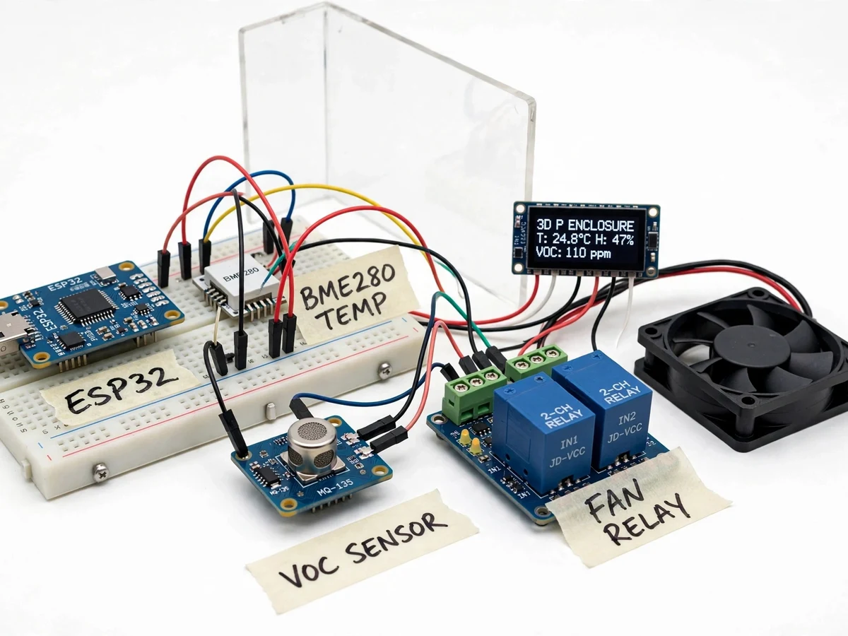
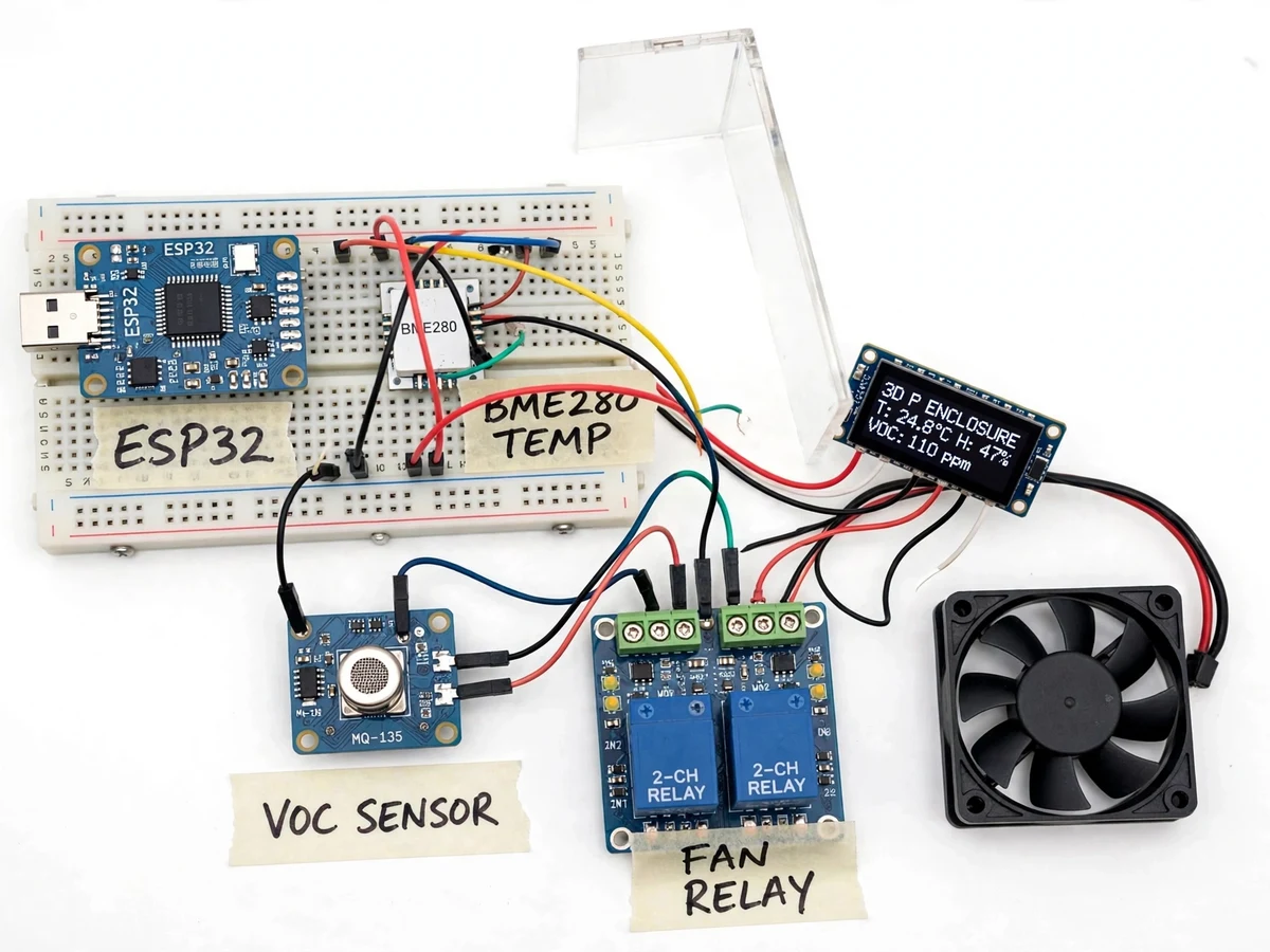
Enclosing a 3D printer improves ABS and ASA prints, but it also traps heat and the volatile compounds filaments release — and most hobby enclosures have no instrumentation at all. Users discover overheating when a print warps, and fumes when the room smells. This project instruments the enclosure: a BME280 measures temperature and humidity, an MQ-135 tracks air-quality trends, and an ESP32 runs the control loop — fan on at temperature or air-quality thresholds, thermal alarm with buzzer at the high limit, everything visible on an OLED and a WiFi dashboard. The report documents what each sensor can and cannot claim: the BME280 is a proper calibrated sensor, while the MQ-135 needs a 24-hour burn-in and yields a relative index, not laboratory ppm. That distinction — plus a fan that demonstrably spins up when you warm the sensor or waft a solvent — makes the demo and the viva both credible.
How it works
- The ESP32 samples the BME280 (temperature, humidity) and the MQ-135 (analog air-quality signal) on a fixed cycle (design target ~5 s).
- The MQ-135 reading is normalized against its burn-in baseline into a relative air-quality index (design target 0–100 scale).
- Temperature and the index are each compared against their on/off threshold pairs with hysteresis.
- When either threshold trips, the relay energizes the 12 V fan; the OLED and dashboard switch fan state to ON with the triggering cause.
- If temperature crosses the separate high-limit, the buzzer sounds and the OLED shows a thermal warning regardless of fan state.
- When readings fall back below the off-points, the fan stops; all transitions are logged with timestamps on the dashboard.
- Thresholds are editable on the WiFi page and apply immediately, so examiners can force a fan cycle during the demo.
Tech stack:
- ESP32 (WiFi-enabled microcontroller)
- BME280 temperature/humidity/pressure sensor
- MQ-135 air-quality gas sensor
- 2-channel 5 V relay module
- 12 V DC cooling fan
- 0.96" OLED display (I2C)
- Piezo buzzer
- Arduino IDE · ESP32 core
| Parameter | Value |
|---|---|
| Controller | ESP32 (dual-core 240 MHz, datasheet) |
| Temperature | BME280, ±0.5 °C (datasheet) |
| Humidity | BME280, ±3 %RH (datasheet) |
| Air quality | MQ-135, relative index after burn-in (not certified ppm) |
| Fan | 12 V DC, relay-switched with hysteresis |
| Display | 0.96" OLED 128x64 (datasheet) |
| Sampling | Approximately 5 s cycle (design target) |
| Alarm | Thermal high-limit + buzzer, buyer-configurable |
| Dashboard | Local WiFi page, live values + event log |
Project features
- [BME280 climate sensing] Temperature (±0.5 °C) and humidity (±3 %RH) from a factory-calibrated sensor — the trustworthy half of the instrument.
- [MQ-135 air-quality trend] Tin-oxide gas sensor tracked as a relative air-quality index after burn-in, used for fan control and alerting, never as certified ppm.
- [Relay fan control] A 2-channel relay drives a 12 V enclosure fan with separate temperature and air-quality thresholds plus hysteresis.
- [Thermal high-limit alarm] Buzzer and OLED warning when temperature crosses the safety limit, independent of the fan loop.
- [OLED live display] Enclosure temperature, humidity, air-quality index and fan state on a 0.96" OLED.
- [WiFi dashboard] The ESP32 hosts a local page with live readings, threshold settings and recent fan/alarm events.
- [Hysteresis control] Separate on/off points per threshold stop the fan from chattering at the boundary — demonstrated live.
- [Burn-in calibration note] A documented MQ-135 burn-in and baseline procedure so the index means something for the buyer's enclosure.
What is included
- Fully wired prototype: ESP32 assembly, BME280, MQ-135, relay module, 12 V fan, OLED, buzzer
- Acrylic enclosure corner panel for the demo arrangement
- ESP32 firmware source code with thresholds and hysteresis logic
- MQ-135 burn-in and baseline calibration procedure
- Wiring diagram and connection table
- Project report PDF (background, sensor theory, methodology, results, limitations)
- PPT presentation for final review
- Viva Q&A preparation document (BME280 vs MQ-135 sensing principles, hysteresis, burn-in)
Limitations & prerequisites
- The MQ-135 yields a relative air-quality index, not certified VOC ppm — the listing never claims laboratory-grade gas measurement, and neither should the student.
- The monitor assists supervision; it does not make an enclosed printer safe to leave unattended — thermal runaway protection remains the printer firmware's job.
- The fan moves air but is not a fume-extraction system; ducting to outdoors is listed as future scope.
- MQ-135 needs the documented burn-in before readings stabilize; first-day numbers are meaningless.
- The demo enclosure corner is a display arrangement, not a full printer enclosure — the buyer mounts sensors in their own enclosure per the guide.
Frequently Asked Questions
What does the MQ-135 actually measure?
It is a tin-oxide semiconductor whose resistance shifts with several gases. After burn-in we track it as a relative air-quality index for fan control — useful and demonstrable, but not a certified ppm measurement, and the report states this explicitly.
How is the fan triggered?
Two independent threshold pairs with hysteresis: one on temperature, one on the air-quality index. Either can start the fan; the OLED and dashboard show which cause fired. Warm the sensor with your hand and watch it respond.
Will it prevent a printer fire?
No — and this is stated plainly. The thermal alarm warns of abnormal heat, but fire safety depends on the printer's own protections and supervision. This is an assistive monitor, not a safety system.
Why hysteresis on the fan control?
Without separate on/off points, a reading hovering at the threshold would chatter the relay on and off. Hysteresis is standard control practice and a solid viva talking point.
Does it need the internet?
No. The dashboard is hosted on the ESP32 on the local WiFi network — no cloud, no account, and it works in the lab offline.
Is this project suitable for a final-year project?
Yes — for Electronics and IoT programs. It pairs a calibrated sensor with a trend sensor honestly, implements hysteresis control, and demonstrates a complete sense-decide-actuate loop. Suitable for B.E./B.Tech final-year projects in Electronics and IoT.
Components & software requirements
- ESP32 (WiFi-enabled microcontroller)
- BME280 temperature/humidity/pressure sensor
- MQ-135 air-quality gas sensor
- 2-channel 5 V relay module
- 12 V DC cooling fan
- 0.96" OLED display (I2C)
- Piezo buzzer
- Arduino IDE · ESP32 core
Delivery information
Built-to-order project. Delivery timeline is shared after order confirmation based on current queue.
Support terms
Complete documentation, setup guide, and viva preparation included. Support for setup and explanation provided.