
More project photos (2)
The problem
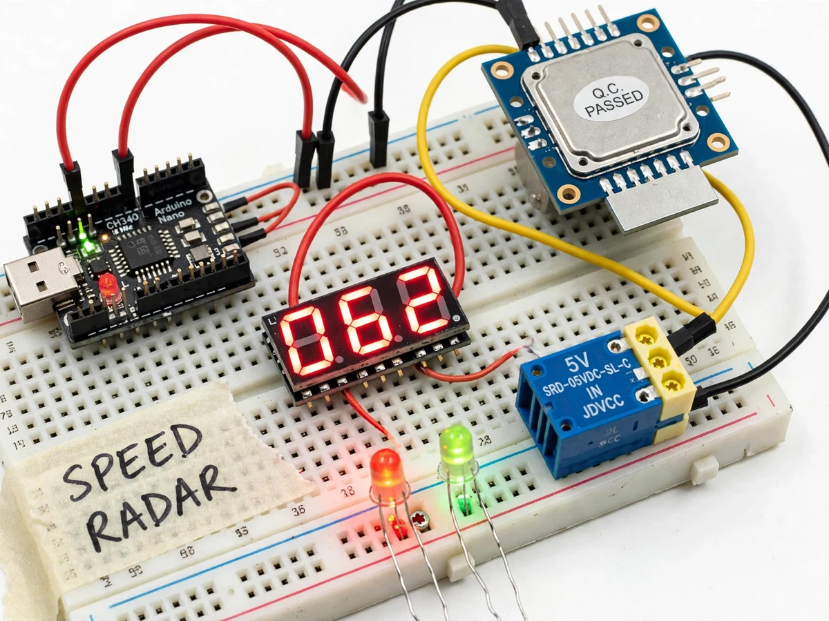
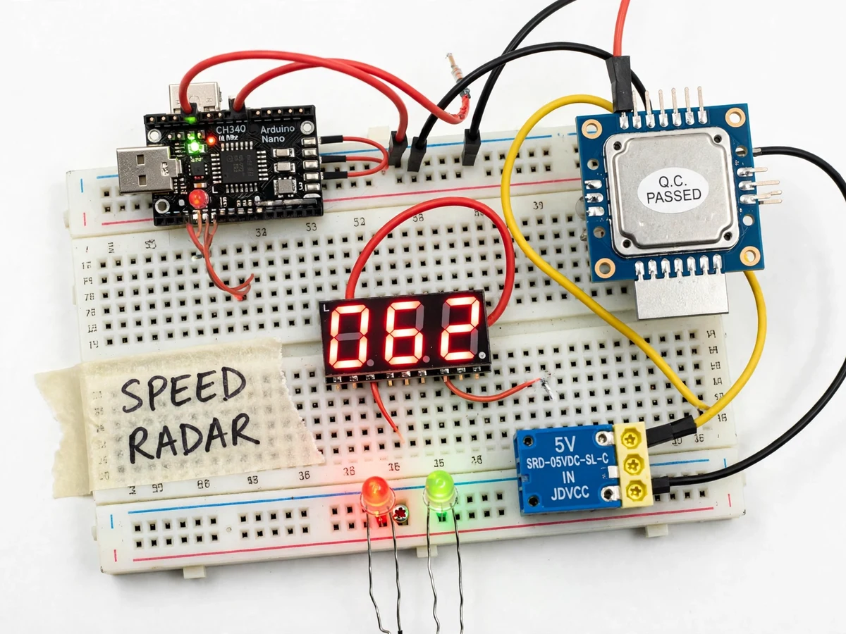
Speeding inside campuses, residential societies and industrial townships is a persistent safety problem, and commercial radar speed displays cost far more than a student or a small institution can justify for a single gate or stretch of road. This project builds that capability from commodity parts: the HB100 microwave Doppler module transmits at 10.525 GHz and returns a tiny intermediate-frequency signal whose frequency is directly proportional to the target's radial speed (about 19.49 Hz per km/h). An Arduino Nano amplifies that microvolt-level signal with an LM358 stage, counts its frequency with an interrupt, converts it to km/h, and drives a large 7-segment display plus green/red status lamps and a buzzer. A campus security gate can set a 30 km/h limit and get an instant, visible, audible warning for every vehicle that crosses it — no camera, no number-plate database, no privacy complications.
Road vehicle reflecting the radar beam back to the module.
Follow the working sequence
How it works
- The HB100 continuously transmits a 10.525 GHz microwave signal toward the road and mixes the reflection with the transmitted wave.
- A moving vehicle shifts the reflected frequency (Doppler effect); the module's IF pin outputs this difference frequency — about 19.49 Hz per km/h of radial speed.
- The LM358 amplifier stage boosts the microvolt-level IF signal and squares it into 5V pulses the Arduino Nano can read.
- The Nano counts pulses with a hardware interrupt over a fixed 1-second window and converts the count to km/h using the calibrated constant.
- The computed speed is written to the 4-digit 7-segment display every second; the green lamp stays lit while the speed is under the limit.
- If the speed exceeds the stored limit, the red lamp and buzzer activate until the vehicle leaves the beam; the limit itself is set with the two buttons and saved to EEPROM.
Tech stack:
- Arduino Nano (ATmega328P)
- HB100 X-band Doppler radar module (10.525 GHz)
- LM358 dual op-amp signal conditioning
- 4-digit 7-segment display (TM1637)
- 5V active buzzer + red/green indicator LEDs
- Push-buttons + EEPROM limit storage
- 5V regulated power supply
- Arduino IDE (C++ firmware)
| Parameter | Value |
|---|---|
| Radar frequency | 10.525 GHz (HB100 datasheet) |
| Supply | 5 V DC regulated (design) |
| Current draw | Approximately 60 mA total (design target) |
| Doppler constant | Approximately 19.49 Hz per km/h (derived from 10.525 GHz) |
| Displayed range | 1–99 km/h (design) |
| Resolution | Approximately 1 km/h (design target) |
| Detection range | Approximately 10–20 m for cars (design target, strongest reflector) |
| Speed limit | 10–80 km/h, default 30 km/h, EEPROM-stored |
| Response | Display update approximately 1 s; buzzer/lamp immediate on crossing |
| Enclosure | Open prototype (weatherproof housing as buyer-side option) |
Project features
- [Doppler radar speed sensing] HB100 X-band module (10.525 GHz) measures true radial speed from the reflected microwave signal — works day and night, through light rain, with no camera and no lighting needed.
- [Live speed display] 4-digit 7-segment display shows the detected speed in km/h in real time, readable from across a gate or road.
- [Configurable speed limit] Two push-buttons set the limit (10–80 km/h); the value is stored in EEPROM so it survives power cuts.
- [Overspeed warning] Red lamp and buzzer fire the moment a vehicle crosses the set limit; green lamp shows all-clear otherwise.
- [Signal conditioning stage] LM358-based amplifier and comparator lift the HB100's microvolt IF output to clean 5V logic the Arduino can count reliably.
- [Calibration mode] A simple drive-by procedure against a GPS speedometer reference trims the Hz-per-km/h constant, documented step by step.
- [Single 5V supply] The whole unit runs from one regulated 5V adapter, drawing roughly 60 mA (design target).
What is included
- Assembled and tested prototype (Arduino Nano, HB100 module, amplifier stage, display, lamps, buzzer)
- Complete firmware source with calibration mode
- Circuit diagram and wiring layout
- Step-by-step calibration guide (GPS-reference drive-by procedure)
- Project report PDF (Doppler theory, signal chain, methodology, results)
- PPT presentation for final review
- Viva Q&A preparation document (Doppler effect, IF amplification, interrupt counting, cosine error)
- Bill of materials with sourcing pointers
Limitations & prerequisites
- The module reports the strongest reflector in its beam — with two vehicles side by side, the reading follows the larger/closer one, not each individually.
- Measured speed is radial speed: at an angle θ to the vehicle's path the reading is actual speed × cos θ, so the unit must face traffic as head-on as practical.
- Heavy rain and dense roadside foliage add noise to the IF signal and shorten the reliable range.
- 10–20 m detection range is a design target for cars; small two-wheelers present a smaller radar cross-section and read at shorter range.
- This is an educational warning display, not a certified enforcement instrument — it cannot issue challans or identify vehicles.
- Allow 1–2 minutes of warm-up after power-on for the oscillator to stabilize before calibrating.
Frequently Asked Questions
How does the Doppler radar measure speed?
The HB100 transmits microwaves at 10.525 GHz. A moving vehicle reflects them back shifted in frequency; the module outputs the difference (the IF signal) at about 19.49 Hz per km/h. The Arduino counts that frequency and converts it to km/h — no camera, no light, no contact with the vehicle.
What is the detection range?
The design target is roughly 10–20 m for cars, the strongest common reflector. Two-wheelers and pedestrians present smaller radar cross-sections and are picked up closer. Range is stated as a design target, not a measured claim.
Can it tell which vehicle is speeding when two pass together?
No. Like all single-beam Doppler units, it reports the strongest reflector in the beam. It is a warning display for gates and campus roads, not a per-vehicle enforcement tool.
How is it calibrated?
A calibration mode in the firmware lets you drive past at a steady GPS-indicated speed (say 30 km/h) and trims the Hz-per-km/h constant until the display matches. The full procedure is in the calibration guide.
Does the angle of the unit matter?
Yes — the physics measures radial speed, so a unit angled at θ to the road reads actual × cos θ. Mount it facing oncoming traffic as directly as possible, and calibrate in the final mounting position.
Is this project suitable for a final-year project?
Yes — for Electronics, Electrical and IoT programs. It combines RF sensing, analog signal conditioning, embedded firmware with interrupts, and a genuinely deployable road-safety application. Suitable for B.E./B.Tech final-year projects in Electronics, Electrical and IoT.
Components & software requirements
- Arduino Nano (ATmega328P)
- HB100 X-band Doppler radar module (10.525 GHz)
- LM358 dual op-amp signal conditioning
- 4-digit 7-segment display (TM1637)
- 5V active buzzer + red/green indicator LEDs
- Push-buttons + EEPROM limit storage
- 5V regulated power supply
- Arduino IDE (C++ firmware)
Delivery information
Built-to-order project. Delivery timeline is shared after order confirmation based on current queue.
Support terms
Complete documentation, setup guide, and viva preparation included. Support for setup and explanation provided.
Download free synopsis (PDF)
Enter your name and email — the synopsis PDF downloads immediately. We may send occasional project updates; no spam, unsubscribe anytime.