
More project photos (3)
The problem
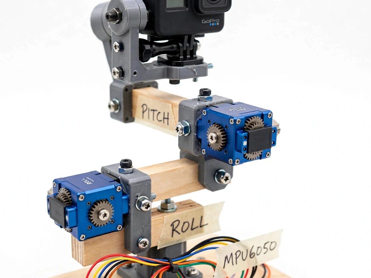
Shaky footage ruins video, and the fix is not software cropping but a stabilized mount: sense the motion, counter-rotate the camera, and the frame stays level while the hand moves. Commercial gimbals do this with brushless motors and high-rate IMUs, but the control principle — measure attitude, compute error, drive actuators in a closed loop — is identical on a student budget. This project implements it with an MPU6050 IMU, an Arduino running a PID controller, and two hobby servos driving a pitch/roll camera frame. The student builds the mechanics, wires the sensor, fuses accelerometer and gyroscope data with a complementary filter, and tunes the PID gains until the camera holds level through deliberate hand movement. The demo is visceral: tilt the base, watch the camera stay put.
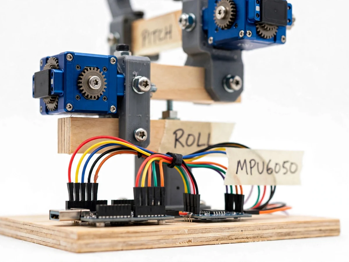
6-axis accel + gyro over I2C; fused by a complementary filter into pitch and roll.
Follow the working sequence
How it works
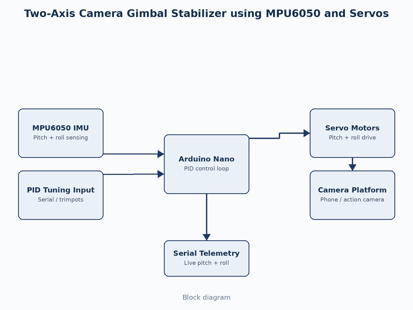
- The MPU6050 streams accelerometer and gyroscope data to the Arduino over I2C at the firmware's control rate.
- A complementary filter fuses the two: the gyro gives fast response, the accelerometer corrects long-term drift, yielding stable pitch and roll angles.
- The PID controller compares the measured angles against the level setpoint and computes the servo correction for each axis.
- The two servos counter-rotate the camera frame in real time, holding the platform level while the base is tilted by hand.
- In follow mode, slow sustained motion is treated as intentional panning and tracked; fast motion is rejected as shake.
- The student runs the disturbance test — tilting the base while logging pitch/roll over serial — and tunes the PID gains for the flattest response.
Tech stack:
- Arduino Nano (ATmega328P)
- MPU6050 6-axis IMU (I2C)
- 2x metal-gear servo motors (pitch/roll)
- Complementary filter + PID control loop
- 3D-printed/wooden two-axis camera frame
- Serial telemetry for tuning plots
- Arduino IDE (C/C++ firmware)
| Parameter | Value |
|---|---|
| Axes | 2 (pitch, roll) |
| IMU | MPU6050, ±250 °/s gyro, ±2 g accel (datasheet ranges) |
| Control rate | Approximately 100 Hz loop (design target) |
| Servo travel | Approximately ±45° per axis (expected, frame-limited) |
| Camera payload | Up to approximately 150 g (phone / action camera, design target) |
| Stabilization | Holds platform within approximately ±2° on gentle hand tilt (design target, buyer-verified) |
| Power | 5 V / 2 A supply for servos, USB for logic |
| Telemetry | Serial pitch/roll stream for tuning plots |
Project features
- [Closed-loop stabilization] MPU6050 senses pitch and roll; a PID loop counter-drives two servos so the camera platform holds its attitude against base movement.
- [Complementary-filter fusion] Accelerometer and gyroscope data are fused to cancel gyro drift and accelerometer noise — the standard student-grade sensor-fusion method, explained in the report.
- [PID tuning interface] Proportional, integral and derivative gains are adjustable over serial (or via trimpots), so the student tunes response vs overshoot themselves and records the results.
- [Two-axis servo drive] Pitch and roll axes driven by metal-gear servos with a balanced 3D-printed/wooden camera frame built for a phone or action camera.
- [Follow mode] Configurable follow mode lets the camera track slow intentional pans while still rejecting fast shake — demonstrating mode logic beyond raw stabilization.
- [Live attitude telemetry] Pitch/roll angles stream over serial for plotting, so the tuning process produces real graphs for the report.
- [Buyer-run tuning procedure] Step-by-step PID tuning guide with a disturbance test the student performs and documents.
What is included
- Working two-axis gimbal prototype (frame, IMU, servos, controller)
- Arduino firmware with complementary filter, PID and follow mode
- Wiring diagram and mechanical assembly documentation
- PID-tuning and disturbance-test procedure
- Project report PDF (IMU theory, sensor fusion, PID control, tuning results template)
- PPT presentation for final review
- Viva Q&A preparation document
Limitations & prerequisites
- Two axes only — yaw drift is not corrected; a three-axis build needs a yaw motor and slip ring.
- Hobby servos are slower and coarser than brushless gimbal motors, so fast deliberate motion will show some lag.
- The ±2° figure is a design target verified by the buyer's own disturbance test, not a laboratory measurement.
- IMU must be calibrated (gyro bias) at each power-up; the firmware includes the routine.
- Outdoor use in wind or on vehicles exceeds the servo authority — the demo is a hand-held indoor rig.
Frequently Asked Questions
How does the stabilization actually work?
The MPU6050 measures how the base tilts; the Arduino computes how far the camera is from level and drives the servos the opposite way, hundreds of times per second. The camera stays level because the corrections cancel the motion.
What is the complementary filter for?
Gyroscopes drift over time and accelerometers are noisy during motion. The filter combines them — trusting the gyro short-term and the accelerometer long-term — to get a stable angle estimate.
Why PID and not just proportional control?
Proportional-only control leaves steady error and oscillates. The integral term removes persistent offset and the derivative term damps oscillation — tuning the three gains is the core learning of the project.
What is follow mode?
A mode where slow, sustained tilts are treated as intentional camera pans and tracked, while fast jitter is still rejected. It shows the controller can distinguish intent from shake.
Can it carry a DSLR?
No — the frame and servos are sized for approximately 150 g (a phone or action camera). Heavier payloads need a redesigned frame and stronger actuators.
Is this project suitable for a final-year project?
Yes — for Electronics, Mechatronics and Robotics programs. It demonstrates IMU interfacing, sensor fusion, closed-loop PID control and servo mechanics in one build. Suitable for B.E./B.Tech final-year projects in Electronics and Communication, Mechatronics and Robotics.
Components & software requirements
- Arduino Nano (ATmega328P)
- MPU6050 6-axis IMU (I2C)
- 2x metal-gear servo motors (pitch/roll)
- Complementary filter + PID control loop
- 3D-printed/wooden two-axis camera frame
- Serial telemetry for tuning plots
- Arduino IDE (C/C++ firmware)
Delivery information
Built-to-order project. Delivery timeline is shared after order confirmation based on current queue.
Support terms
Complete documentation, setup guide, and viva preparation included. Support for setup and explanation provided.
Download free synopsis (PDF)
Enter your name and WhatsApp number — the synopsis PDF downloads immediately. We may send occasional project updates on WhatsApp; no spam.