
More project photos (3)
The problem
Inductive loads — induction motors, transformers, welding sets, fluorescent lighting — consume reactive power that does no useful work but still flows through cables, switchgear and transformers, increasing current, copper losses, voltage drop and the maximum-demand charges utilities bill. Correcting the power factor with shunt capacitors is standard practice, but conventional contactor-switched banks are slow and slam capacitors onto the bus with inrush transients and contact wear. Thyristor-switched capacitor (TSC) banks solve this by switching each capacitor step at voltage zero-crossing: no inrush, no arcing, and response within a cycle or two, which is why TSC/TCR schemes dominate modern dynamic compensation. This project makes that industrial technique demonstrable on a bench: a single-phase prototype where an Arduino samples voltage and current, computes the displacement power factor, and switches three capacitor steps through optically isolated thyristor switches at zero-crossing, holding the power factor near unity as a variable inductive test load changes.
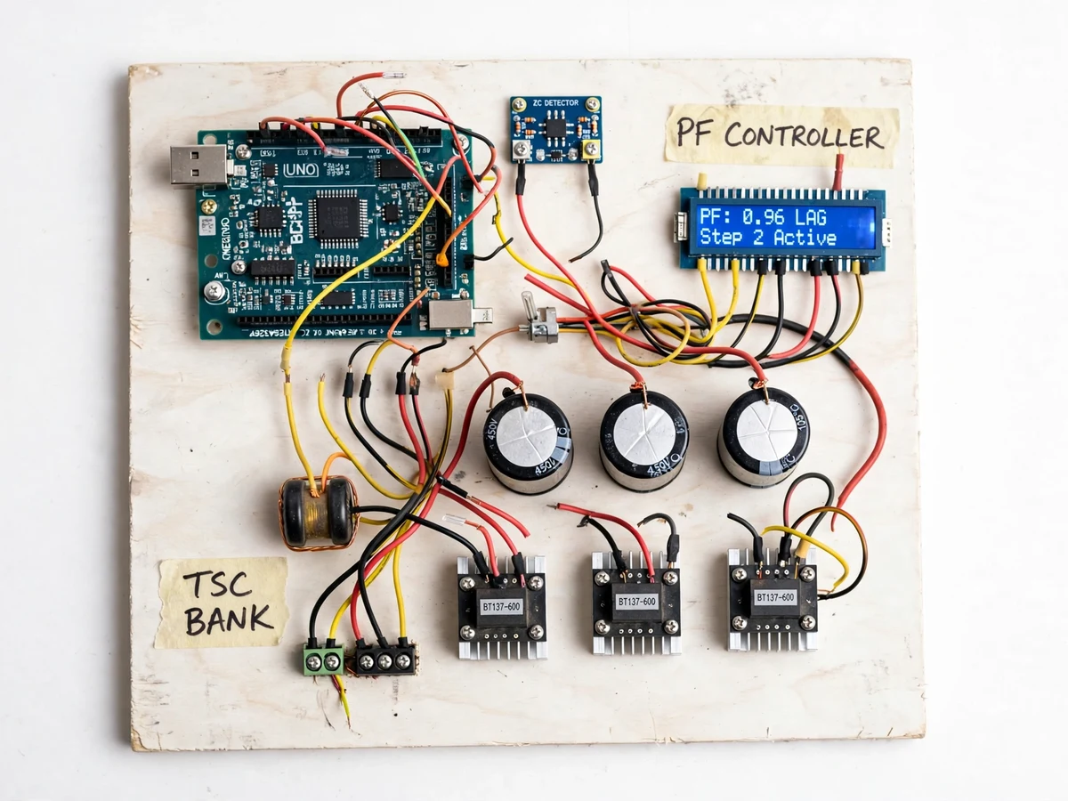
Isolated voltage and current transformers feed scaled-down mains waveforms to the controller ADC.
Follow the working sequence
How it works
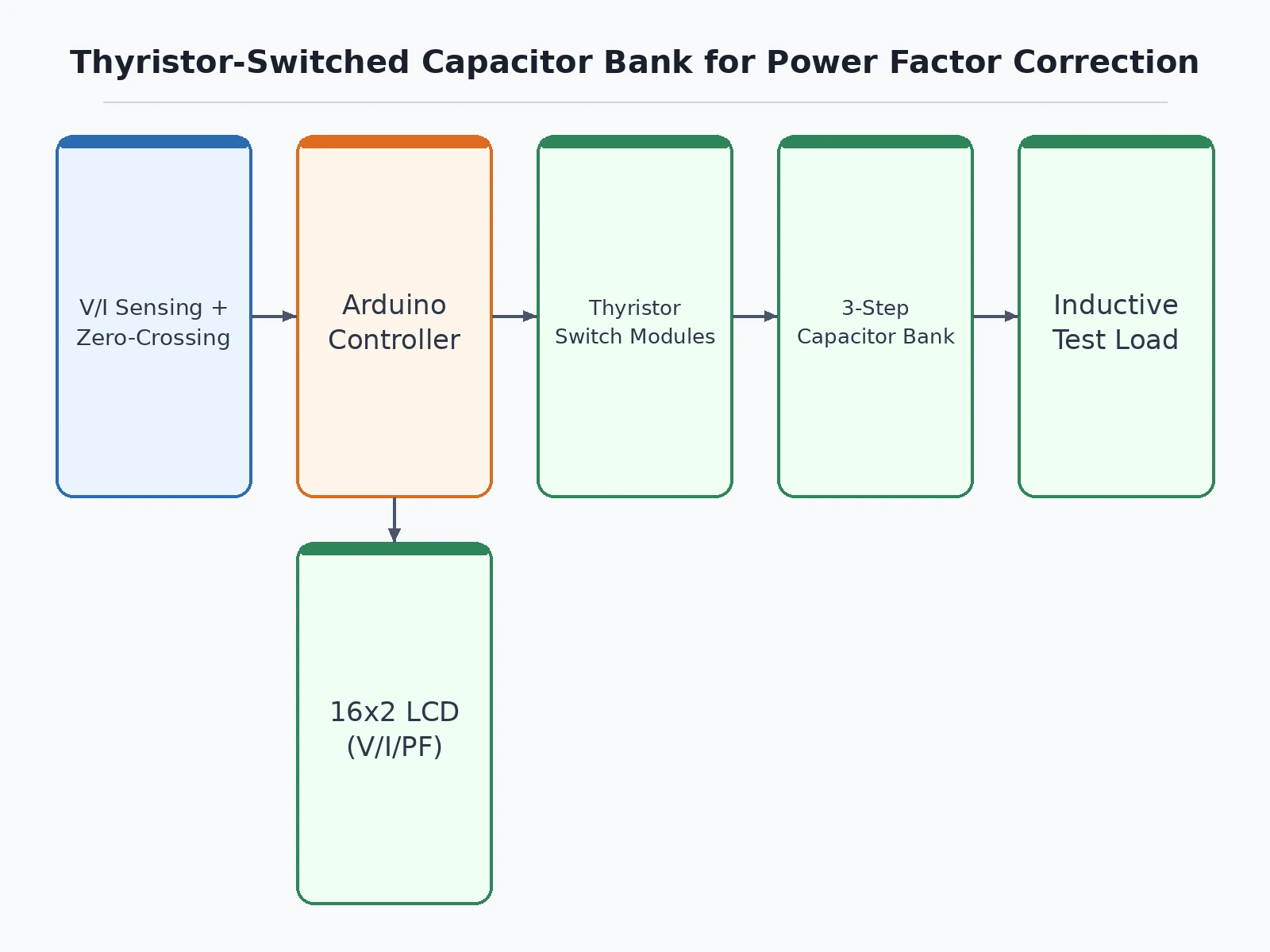
- Voltage and current transformers (or isolated sense dividers) feed scaled-down voltage and current waveforms to the Arduino's ADC.
- The firmware detects voltage zero-crossings and measures the time delay to the current zero-crossing, converting it into the phase angle and hence the displacement power factor.
- When the measured power factor falls below the configured target minus hysteresis, the controller selects the next capacitor step to switch in.
- Firing pulses are issued to the opto-isolated thyristor drivers exactly at the next voltage zero-crossing, connecting the capacitor step with no transient.
- The controller re-measures after each switching event; if the power factor overshoots (leading), it steps capacitors back out, again at zero-crossing.
- The LCD continuously shows voltage, current, power factor, active and reactive power estimates, and which steps are engaged.
- If the bus voltage exceeds the overvoltage setpoint, all steps are shed immediately and a fault lamp lights until reset.
Tech stack:
- Arduino Uno (ATmega328P)
- Zero-crossing detector (optocoupler-based) for timing reference
- Back-to-back thyristor (SCR pair) or TRIAC switch modules with opto-isolated drivers
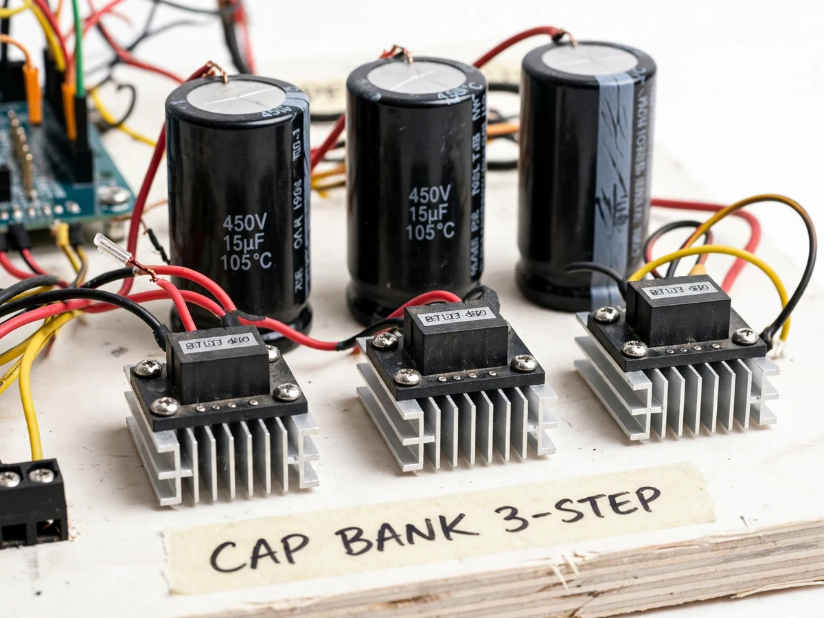
- Stepped shunt capacitor bank (3 steps) with discharge resistors
- Voltage and current sensing stage (isolated)
- 16x2 character LCD
- Arduino IDE (C/C++ firmware)
- Variable inductive test load (choke + lamp bank)
| Parameter | Value |
|---|---|
| Controller | Arduino Uno (ATmega328P) |
| Supply | 230 V AC single-phase test circuit; 5 V DC logic |
| Capacitor steps | 3 independently switched steps (design values sized for the test load; exact µF set during build) |
| Switching device | Back-to-back thyristors / TRIACs, opto-isolated gate drive, fired at voltage zero-crossing |
| Measured quantities | RMS voltage, RMS current, displacement power factor, estimated kW/kVAr |
| Target power factor | Configurable in firmware; design target ≥ 0.95 lagging under test-load variation |
| Step response | Switching decision within a few mains cycles of a load change (design target) |
| Display | 16x2 LCD: V, I, PF, kW, kVAr, engaged steps |
| Protection | Capacitor discharge resistors; overvoltage step-shed; fused test circuit |
Project features
- [Zero-crossing thyristor switching] Each capacitor step switches through back-to-back thyristors fired only at voltage zero-crossing, so steps engage with no inrush transient and no contact wear — the core TSC principle.
- [Automatic power-factor measurement] Voltage and current are sampled on the Arduino and the displacement power factor is computed from the phase angle, with a live readout on the LCD.
- [Three-step capacitor bank] Three switched capacitor steps give seven discrete compensation levels, letting the controller track a varying inductive load and hold the power factor near the target.
- [Configurable target power factor] The target power factor and step-switching hysteresis are set in firmware, so the student can demonstrate under-compensation, correct compensation and the hunting behavior of a badly tuned controller.
- [Overvoltage and discharge protection] Each capacitor carries a discharge resistor, and the controller sheds steps if the bus voltage rises above the set limit, demonstrating safe capacitor-bank practice.
- [Manual and automatic modes] A selector switch allows manual step switching for teaching, while automatic mode runs the closed-loop controller for the main demonstration.
- [Inductive test load rig] A variable inductive load (choke plus lamp bank) is included so the examiner can watch the power factor dip and the controller bring it back.
What is included
- Working TSC power-factor correction prototype (Arduino, zero-cross detector, thyristor switch modules, capacitor bank, sensors, LCD, test load)
- Complete firmware source code (PF measurement, step logic, zero-cross firing, LCD)
- Circuit and wiring documentation with capacitor sizing notes
- Component list with voltage/current ratings
- Calibration and tuning procedure (buyer-run: verify switching levels and target PF)
- Project report PDF (reactive power theory, TSC principle, methodology, test procedure)
- PPT presentation for final review
- Viva Q&A preparation document (power factor, displacement vs true PF, TSC vs contactor banks, zero-crossing)
- Setup and demonstration guide
Limitations & prerequisites
- This is an academic demonstration prototype, not a utility-grade compensation panel; it must not be connected to real industrial or building distribution boards.
- Capacitor step values are design-sized for the supplied test load; compensation range and final target PF are verified by the buyer's own tuning procedure, not pre-measured.
- Single-phase demonstration only; three-phase TSC with per-phase control is a possible extension, not part of the base build.
- Thyristor modules need adequate heatsinking at sustained load — thermal sizing notes are included, but continuous full-load operation is not a demo requirement.
- Displacement power factor is computed (fundamental); harmonic distortion effects on true power factor are noted as a limitation, not measured.
Frequently Asked Questions
Why thyristors instead of contactors for switching capacitors?
Contactor-switched capacitors suffer inrush transients and contact wear, and switch slowly. Thyristors fired at voltage zero-crossing connect the capacitor with no transient and respond within cycles — this is the TSC principle used in industrial dynamic compensation, and this project demonstrates it.
How is the power factor measured?
Voltage and current waveforms are sampled, zero-crossings detected, and the phase delay between them gives the displacement power factor. The LCD shows V, I, PF and estimated kW/kVAr continuously.
How many capacitor steps does it use?
Three independently switched steps, giving seven compensation levels. Step values are sized for the test load and the switching hysteresis is configurable in firmware.
Can this be connected to a real factory panel?
No. It is an academic prototype sized for a bench test load. Real installations need rated switchgear, protection coordination and a licensed electrician.
What are the main limitations?
Single-phase demo; capacitor values are design-sized, not measured at build; only displacement PF is computed; thyristors need heatsinks for sustained operation.
Is this project suitable for a final-year project?
Yes — for Electrical programs. It covers reactive power, zero-crossing switching, closed-loop step control and capacitor-bank safety, all strong viva material. Suitable for B.E./B.Tech final-year projects in Electrical engineering.
Components & software requirements
- Arduino Uno (ATmega328P)
- Zero-crossing detector (optocoupler-based) for timing reference
- Back-to-back thyristor (SCR pair) or TRIAC switch modules with opto-isolated drivers
- Stepped shunt capacitor bank (3 steps) with discharge resistors
- Voltage and current sensing stage (isolated)
- 16x2 character LCD
- Arduino IDE (C/C++ firmware)
- Variable inductive test load (choke + lamp bank)
Delivery information
Built-to-order project. Delivery timeline is shared after order confirmation based on current queue.
Support terms
Complete documentation, setup guide, and viva preparation included. Support for setup and explanation provided.
Download free synopsis (PDF)
Enter your name and WhatsApp number — the synopsis PDF downloads immediately. We may send occasional project updates on WhatsApp; no spam.