
More project photos (2)
The problem
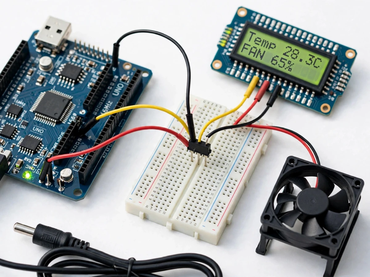
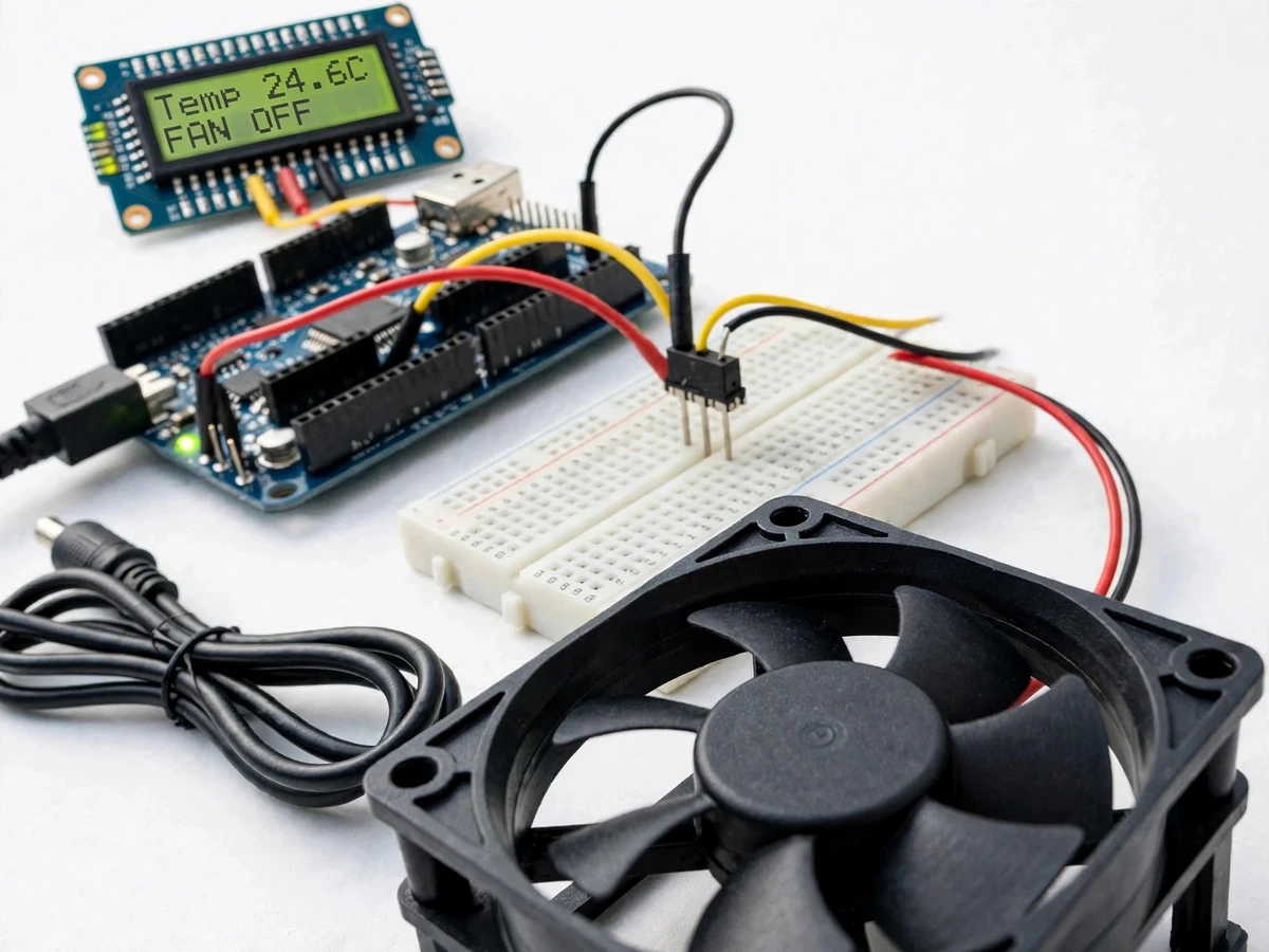
A temperature controlled fan project is a system that measures room temperature and changes fan speed automatically instead of running at one fixed speed. An LM35 sensor reports the temperature to an Arduino Uno, which converts the reading into a PWM duty cycle and drives a 12 V DC fan faster as the room warms and slower as it cools.
| Setup | How speed is chosen | What a visitor sees | Honest limit |
|---|---|---|---|
| Temperature controlled fan in this build | Measured temperature sets the PWM duty cycle through a ramp table | Temperature and fan speed percentage change together on the LCD | A small demonstrator fan cools a bench setup, not a whole room |
| Always-on fan | Runs at full speed regardless of temperature | Constant airflow and noise even when the air is already cool | Energy and comfort are wasted whenever full speed is not needed |
| Manual speed control | A person turns a knob or flips a switch | Speed changes only when someone notices the heat and acts | Cooling arrives late and stops abruptly instead of easing with temperature |
Rooms warm up, and a fixed-speed fan answers that change with only two choices: full speed or off. A temperature controlled fan removes that blunt choice by letting the measured temperature decide the speed, so cooling effort follows actual heat instead of a switch position. In a study room, a workshop corner, or a small equipment enclosure, a fan left running at full speed wastes energy and creates draught and noise when the air is cool, while a fan switched off stays off until someone notices the heat and changes it. The gap between those two states is where comfort and energy are lost: cooling arrives late, runs harder than needed, then stops abruptly instead of easing down as the temperature falls. A temperature controlled fan closes that gap with a simple closed loop — sense the temperature, set a proportional speed, and display both numbers — so the response is gradual and easy to check at a glance.
Analogue temperature sensor whose output voltage rises 10 mV per degree Celsius.
Follow the working sequence
How it works
The chain runs from heat in the air to motion in the fan through four stages. The LM35 sensor produces an output voltage that rises by 10 mV for every degree Celsius, so room temperature becomes an electrical signal the controller can read. The Arduino Uno reads that voltage on an analogue input, averages several successive readings, and converts the result into a temperature in degrees Celsius. Firmware compares the temperature against a ramp table: below the lower threshold the fan stays off, between thresholds the PWM duty cycle rises with temperature, and above the upper threshold the fan runs at full duty cycle. A MOSFET driver stage switches the 12 V DC fan at that duty cycle, and the LCD updates with the live temperature and fan speed percentage, closing the loop in a form a visitor can watch.
- The builder mounts the LM35 on the breadboard away from the direct draught of the fan, wires its supply, ground, and output pins to the Arduino Uno, and adds a small decoupling capacitor across the sensor supply so fan switching does not disturb the analogue reading.
- The builder wires the MOSFET driver stage between a PWM output pin and the 12 V DC fan, keeping the fan supply separate from the controller supply so fan current never flows through the controller pins.
- The builder connects the 16 by 2 character LCD and confirms the display layout, so temperature in degrees Celsius and fan speed percentage are never confused on screen.
- The builder loads the firmware, which reads the LM35, averages successive readings, converts the average into degrees Celsius, and looks up the matching PWM duty cycle in the ramp table.
- The builder tests the thresholds in order: fan off in cool air, gentle start just above the lower threshold, visibly faster running as the sensor is warmed, and full speed above the upper threshold.
- The builder runs the fan-on and fan-off comparison test, recording the temperature trace with the fan held off and then under automatic control, and notes the sensor placement and averaging settings alongside every result.
- The builder writes up the results honestly, including the design-target thresholds, the sensor accuracy limit, and every condition under which the displayed temperature should not be trusted.
Tech stack:
- Arduino Uno · ATmega328P controller board
- LM35 temperature sensor · analogue voltage output sensing
- 12 V DC fan · PWM speed-controlled cooling load
- 16 by 2 character LCD · live temperature and fan-speed display
- MOSFET driver stage · PWM fan switching and protection
- Breadboard and jumper wiring · prototype assembly
- 12 V DC adapter · fan and driver power supply
- Arduino IDE firmware · temperature reading and PWM control
| Parameter | Value |
|---|---|
| Build type | Bench hardware prototype · Arduino Uno plus LM35 plus DC fan plus LCD (design target) |
| Sensor | LM35 precision temperature sensor · 3-pin analogue device (Datasheet value) |
| Sensor output | 10 mV per degree Celsius (Datasheet value) |
| Sensor range | Minus 55 degrees Celsius to 150 degrees Celsius (Datasheet value) |
| Sensor accuracy | Plus or minus 0.5 degrees Celsius at 25 degrees Celsius (Datasheet value) |
| Controller | Arduino Uno · ATmega328P · 5 V logic (Datasheet value) |
| Fan | 12 V DC fan · PWM speed control (design target) |
| Fan-off threshold | Fan off below about 28 degrees Celsius (Design target) |
| Full-speed threshold | Full PWM duty cycle above about 40 degrees Celsius (Design target) |
| Display | 16 by 2 character LCD · temperature in degrees Celsius plus fan speed percentage (design target) |
| Fan driver | MOSFET switching stage · driven from a PWM output pin (design target) |
| Power | 12 V DC adapter for the fan stage · 5 V USB supply for the controller (design target) |
| Reading method | Averaged over 10 successive readings before each speed decision (design target) |
| Builder note | On the bench build, placing the LM35 in the direct draught of the fan made the displayed temperature fall even while the room stayed warm, so the sensor is mounted away from the airflow, readings are averaged before the PWM duty cycle is set, and a small decoupling capacitor across the sensor supply keeps the analogue reading steady when the fan switches (builder observation) |
Project features
Four capabilities carry the build. Analogue temperature sensing with averaged readings gives the controller a steady temperature value instead of a jittery single sample, because the firmware averages successive LM35 readings before any speed decision is made. A PWM ramp table turns that temperature into a smooth fan-speed curve, so the fan starts gently, rises with heat, and reaches full speed only at the top of the range instead of jumping between off and full. A live LCD display shows the measured temperature beside the fan speed percentage, so every change in speed can be traced to a number on screen. A fan-on and fan-off comparison test completes the set, letting a visitor run the same warm-up twice — once with the fan held off, once under automatic control — and compare how the temperature behaves in each case.
- [Analogue LM35 temperature sensing with averaged readings] The LM35 output voltage rises with temperature, and the firmware averages successive readings before converting the result into degrees Celsius, so brief electrical noise does not jerk the fan speed up and down — implemented in the base build.
- [PWM ramp table for smooth speed control] A ramp table maps temperature bands to PWM duty cycle values, so the fan starts gently above the lower threshold, rises steadily with heat, and reaches full duty cycle only above the upper threshold — implemented in the base build.
- [Live temperature and fan-speed LCD display] A 16 by 2 character LCD shows the measured temperature beside the fan speed percentage at all times, so the link between heat and speed is visible rather than assumed — implemented in the base build.
- [Fan-off, ramping, and full-speed states] The firmware holds three clear states — fan off below the lower threshold, ramping between thresholds, and full speed above the upper threshold — so the behaviour at any temperature can be predicted before testing — implemented in the base build.
- [MOSFET fan driver stage] A MOSFET switching stage drives the 12 V DC fan from the controller PWM output, keeping the higher fan supply current off the controller pins — implemented in the base build.
- [Fan-on and fan-off comparison test] The same warm-up run is repeated with the fan held off and then under automatic control, so the effect of temperature-based control can be shown by comparing the two temperature traces — implemented in the base build.
- [Threshold adjustment through firmware constants] The lower and upper temperature thresholds live as named constants in the firmware, so they can be retuned for a different room or enclosure without rewiring — implemented in the base build.
- [Remote monitoring and multi-fan control] Future scope only, not implemented: wireless temperature reporting and control of several fans from one controller are extensions with their own hardware and testing, not features the base build claims.
What is included
- Complete fabricated temperature-controlled fan prototype (Arduino Uno, LM35 sensor, MOSFET driver stage, 12 V DC fan, 16 by 2 character LCD, breadboard wiring, 12 V DC adapter)
- Sensing and PWM firmware (averaged LM35 reading, temperature conversion, ramp-table duty cycle, LCD formatting, fan-on and fan-off test mode)
- Circuit and wiring documentation (sensor placement, driver wiring, separate fan and controller supplies, decoupling note)
- Setup and testing guide (threshold test procedure, fan-on and fan-off comparison test, sensor-placement pitfall notes)
- Project report PDF (temperature sensing background, ramp-table design, test procedure, honest observations)
- PPT presentation for final review
- Viva Q&A preparation document (LM35 interfacing, analogue-to-digital conversion, PWM motor control, LCD interfacing, threshold design)
- Ordering by quotation: scope, price and delivery timeline are confirmed with a quotation with scope, price and delivery timeline on WhatsApp enquiry
Limitations & prerequisites
- Small demonstrator fan only: the 12 V DC fan cools a bench setup and proves the control loop, and it must never be presented as room air-conditioning or a replacement for a ceiling fan.
- Thresholds are design targets, not calibrated guarantees: the fan-off point near 28 degrees Celsius and the full-speed point near 40 degrees Celsius are starting values that need retuning for a different room, enclosure, or sensor position.
- Sensor accuracy bounds fine control: the LM35 is accurate to plus or minus 0.5 degrees Celsius at 25 degrees Celsius, so thresholds set only a degree or two apart cannot be trusted to behave distinctly.
- Sensor placement changes the reading: a sensor sitting in the fan draught, against a warm surface, or beside a heat source reports a local temperature, not the room temperature, and the report states this plainly.
- Partial-speed fan noise: a fan driven by PWM can hum or buzz at intermediate duty cycles, and the effect varies with the fan, so quiet operation at every speed is not promised.
- Academic prototype, not a certified product: the build needs supervision during demonstrations, the fan supply wiring must be checked before power-up, and the unit carries no safety certification.
Frequently Asked Questions
Is this project suitable for a final-year project?
Yes, for Electronics / E&TC programmes, because it combines analogue temperature sensing, microcontroller firmware, PWM motor control, and live LCD interfacing in one working prototype that a reviewer can test directly. Warming the sensor and watching the fan ramp up gives a clear review thread: how the LM35 voltage becomes a temperature, how the ramp table turns that temperature into a duty cycle, and where a small demonstrator honestly stops. The build also gives a reviewer something measurable to question, from the sensor voltage at a given temperature to the duty cycle at each threshold, rather than a claim that must be taken on trust.
How does the LM35 sensor control the fan speed?
The LM35 produces an output voltage that rises by 10 mV for every degree Celsius, and the Arduino Uno reads that voltage, averages successive readings, and converts the result into a temperature. Firmware then looks up the temperature in a ramp table and sets the PWM duty cycle for the fan, so speed rises smoothly with heat instead of switching between off and full. Because the duty cycle rises in steps with temperature, the fan never jumps straight from still to full speed, and the LCD makes each step visible as it happens.
At what temperatures does the fan switch on and reach full speed?
The fan stays off below about 28 degrees Celsius, ramps up between the lower and upper thresholds, and reaches full PWM duty cycle above about 40 degrees Celsius. Both thresholds are design targets, not measured guarantees, and they live as named constants in the firmware, so they can be retuned for a different room or enclosure without rewiring the prototype. Testing starts in cool air with the fan off, then warms the sensor gradually, so each threshold can be confirmed in turn before the comparison test runs.
What does the LCD display show?
The 16 by 2 character LCD shows the measured temperature in degrees Celsius beside the fan speed percentage, updating continuously as the temperature changes. That pairing is the point of the display: a visitor can watch a temperature rise, see the percentage climb with it, and hear the fan follow, which makes the whole control loop checkable at a glance. If either number looks wrong during testing, the wiring, the sensor position, and the threshold constants give three clear places to check before anything else is changed.
Can the temperature thresholds be changed for a different room?
Yes, by editing the named threshold constants in the firmware and reloading the controller, with no wiring change needed for a threshold change alone. A room that runs warmer or cooler than the bench setup may need a different lower threshold so the fan does not sit off or run constantly, and the testing guide covers retesting the full ramp after any threshold change. A threshold change alone needs no rewiring, but the fan-off point should still be checked in the actual room, since draughts and sunlight shift the sensor reading.
Will this fan cool a whole room?
No, and the build never claims otherwise: the 12 V DC fan is a bench demonstrator load that proves temperature-based speed control, not a room-cooling appliance. It suits a small enclosure, a study desk setup, or a bench demonstration, while cooling a room would need a larger fan, proper airflow design, and its own safety testing, which is future scope rather than part of the base build. For a larger space, the same sensing and ramp-table approach could drive a bigger fan, but that variant would need its own driver sizing and safety checks.
Components & software requirements
- Arduino Uno · ATmega328P controller board
- LM35 temperature sensor · analogue voltage output sensing
- 12 V DC fan · PWM speed-controlled cooling load
- 16 by 2 character LCD · live temperature and fan-speed display
- MOSFET driver stage · PWM fan switching and protection
- Breadboard and jumper wiring · prototype assembly
- 12 V DC adapter · fan and driver power supply
- Arduino IDE firmware · temperature reading and PWM control
Delivery information
Built-to-order project. Delivery timeline is shared after order confirmation based on current queue.
Support terms
Complete documentation, setup guide, and viva preparation included. Support for setup and explanation provided.
Download free synopsis (PDF)
Enter your name and WhatsApp number — the synopsis PDF downloads immediately. We may send occasional project updates on WhatsApp; no spam.