
More project photos (2)
The problem
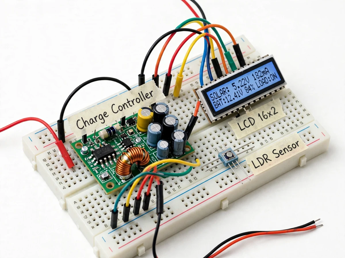
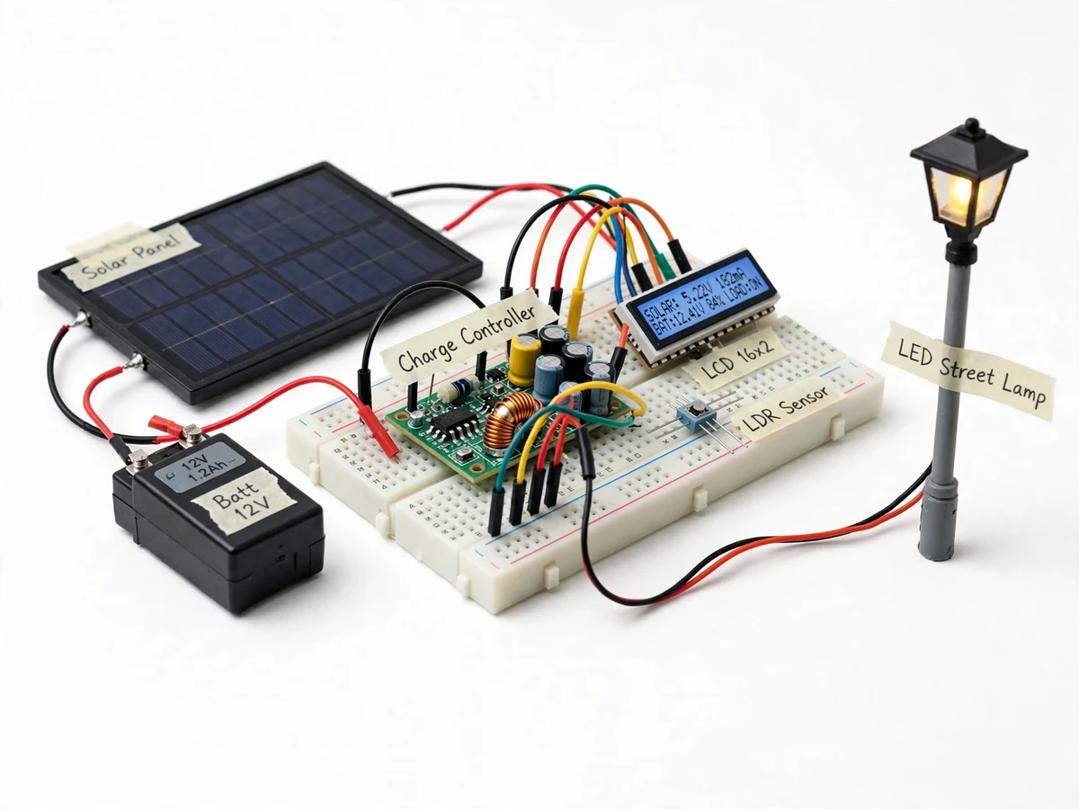
A solar street light looks simple — panel, battery, lamp — but the part that decides whether the battery survives two years or two months is the charge controller. This project builds that controller. A buck/PWM charging stage takes the solar panel input and charges a 12 V battery through three-stage logic (bulk, absorption, float) with temperature-compensated setpoints; an LDR plus panel-voltage sensing detects dusk and switches the LED lamp driver on, with a configurable dimming schedule (full brightness at dusk, dimmed after midnight, bright again before dawn). Protection is the core engineering: overcharge cutoff, deep-discharge load disconnect with hysteresis, short-circuit and reverse-polarity protection on the panel input. An LCD shows panel voltage, battery voltage, charging stage and load state, and the firmware logs daily charge/discharge amp-hours for the report's data section.
How it works
- The controller continuously measures panel voltage, battery voltage and charge current through its sensing dividers and shunt.
- In daylight with the battery low, it runs bulk charging (maximum PWM duty); as voltage rises it transitions to absorption (constant voltage) then float (trickle) — the classic three-stage profile.
- Panel voltage falling below the dusk threshold (confirmed by the LDR) switches the LED driver on; rising panel voltage at dawn switches it off.
- The dimming schedule modulates LED PWM duty by time: full at dusk, dimmed through the configured midnight window, full again before dawn.
- If battery voltage hits the deep-discharge cutoff, the load disconnects with hysteresis and stays off until the battery recovers; overcharge terminates charging.
- Daily amp-hour totals accumulate in EEPROM and display on the LCD, documenting the energy balance for the report.
Tech stack:
- Arduino/ATmega-class controller (or ESP32 variant)
- PWM buck charging stage (MOSFET + inductor + diode)
- 12 V solar panel input (demo-scale)
- 12 V lead-acid/Li-ion battery (demo-scale)
- LDR + panel-voltage dusk sensing
- Constant-current LED driver stage
- 16x2 character LCD
- Arduino IDE (C/C++ firmware)
| Parameter | Value |
|---|---|
| Charging | PWM buck, three-stage: bulk/absorption/float, temperature-compensated setpoints |
| Battery | 12 V class (lead-acid or Li-ion chemistry set in firmware); overcharge + deep-discharge protection |
| Dusk sensing | Panel voltage + LDR with hysteresis; flicker guard |
| Lamp | Constant-current LED driver, PWM dimming schedule (buyer-configured profile) |
| Protection | Overcharge cutoff, deep-discharge disconnect, reverse-polarity, short-circuit |
| Logging | Daily charge/discharge Ah in EEPROM + LCD status |
| Power | Demo-scale panel and battery; prototype is a bench model, not a pole installation |
Project features
- [Three-stage charging] Bulk, absorption and float stages with temperature-compensated setpoints, implemented in firmware around a PWM buck charging stage.
- [Dusk-to-dawn lamp control] Panel-voltage + LDR sensing detects dusk; the LED driver switches on automatically and off at dawn with hysteresis against flicker.
- [Midnight dimming schedule] Configurable dimming profile (e.g. full → 50% after midnight → full before dawn) via PWM on the LED driver, extending battery runtime.
- [Battery protection] Overcharge cutoff, deep-discharge load disconnect with hysteresis, and reverse-polarity protection on the panel input.
- [LED constant-current drive] The lamp is driven by a constant-current stage sized for the LED string, not a bare resistor — proper LED practice.
- [Charge logging] Daily charged/discharged amp-hours are logged to EEPROM and shown on the LCD, giving the report real data to discuss.
- [LCD system status] Panel voltage, battery voltage, charging stage and load state on a 16x2 LCD for a readable demo.
What is included
- Working charge-controller prototype (controller board, buck charging stage, LED driver, LDR, LCD, demo panel/battery/lamp)
- Complete firmware source code (three-stage charging, dusk logic, dimming schedule, protection, logging)
- Circuit and wiring documentation with power-stage design notes
- Component list with ratings
- Setpoint configuration and demo procedure guide
- Project report PDF (solar charging background, three-stage and LED-drive theory, methodology, test procedure)
- PPT presentation for final review
- Viva Q&A preparation document (charge stages, buck conversion, battery protection, dusk sensing)
- Setup and demonstration guide
Limitations & prerequisites
- Bench-scale prototype with demo-size panel and battery; it is not a pole-mounted street-light installation and is not weatherproofed.
- Charging setpoints are design values configured for the demo battery chemistry — the buyer sets them for their own battery; no universal-battery claims.
- PWM charging is not MPPT: the report explains the difference honestly and lists MPPT as future scope.
- Dimming schedules and dusk thresholds are buyer-configured; actual night runtime depends on the panel/battery sizing the buyer chooses.
- Efficiency figures are design estimates from the power-stage design, not measured lab results.
Frequently Asked Questions
What does the controller do?
It charges a 12 V battery from a solar panel through bulk/absorption/float staging, protects against overcharge and deep discharge, and runs the LED lamp dusk-to-dawn with a dimming schedule.
Is this MPPT?
No — it is a PWM three-stage charger, and the report says so explicitly. MPPT tracking is documented as future scope.
How does it know it's dusk?
Panel voltage falling below a threshold, confirmed by an LDR, with hysteresis so passing clouds don't flicker the lamp.
Can it power a real street light?
The prototype is bench-scale with demo-size components. The design notes cover how to scale the power stage, but a pole installation is the buyer's deployment.
What are the main limitations?
Bench scale, buyer-set battery setpoints, PWM not MPPT, design-estimate (not measured) efficiency.
Is this project suitable for a final-year project?
Yes — for IoT and Embedded Systems programs. It combines power electronics, battery management, dusk sensing and honest charge-stage theory, all strong viva material. Suitable for B.E./B.Tech final-year projects in IoT and Embedded Systems.
Components & software requirements
- Arduino/ATmega-class controller (or ESP32 variant)
- PWM buck charging stage (MOSFET + inductor + diode)
- 12 V solar panel input (demo-scale)
- 12 V lead-acid/Li-ion battery (demo-scale)
- LDR + panel-voltage dusk sensing
- Constant-current LED driver stage
- 16x2 character LCD
- Arduino IDE (C/C++ firmware)
Delivery information
Built-to-order project. Delivery timeline is shared after order confirmation based on current queue.
Support terms
Complete documentation, setup guide, and viva preparation included. Support for setup and explanation provided.