
More project photos (2)
The problem
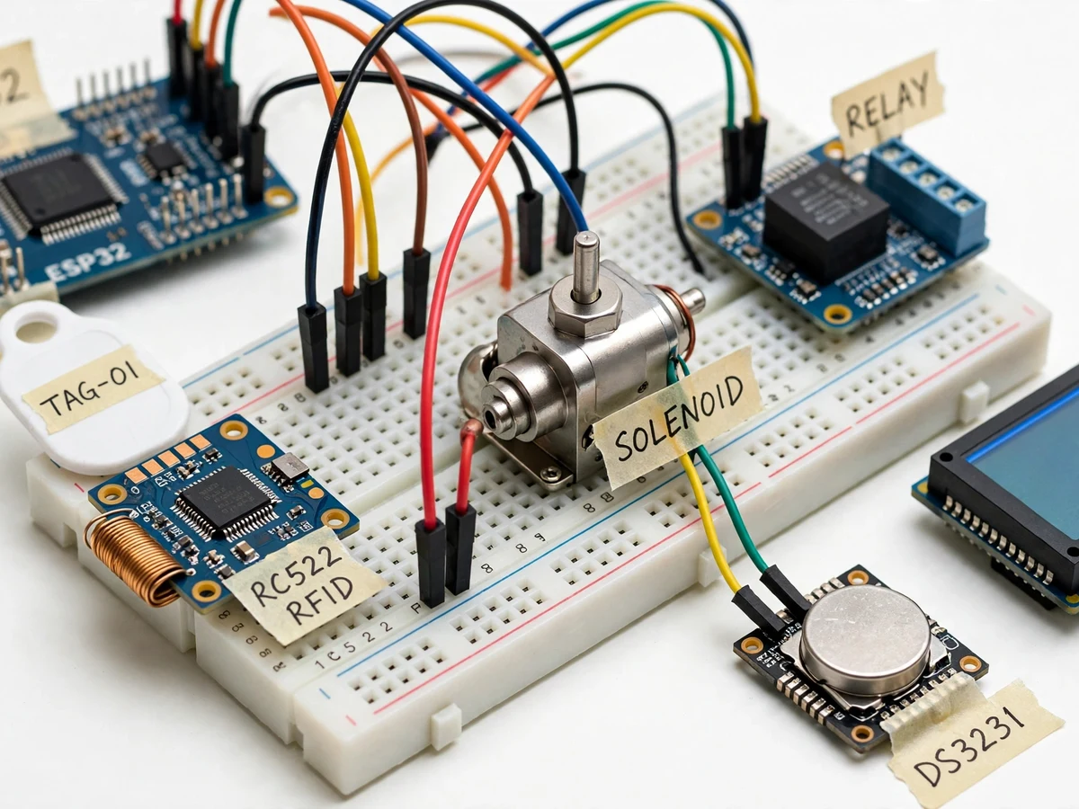
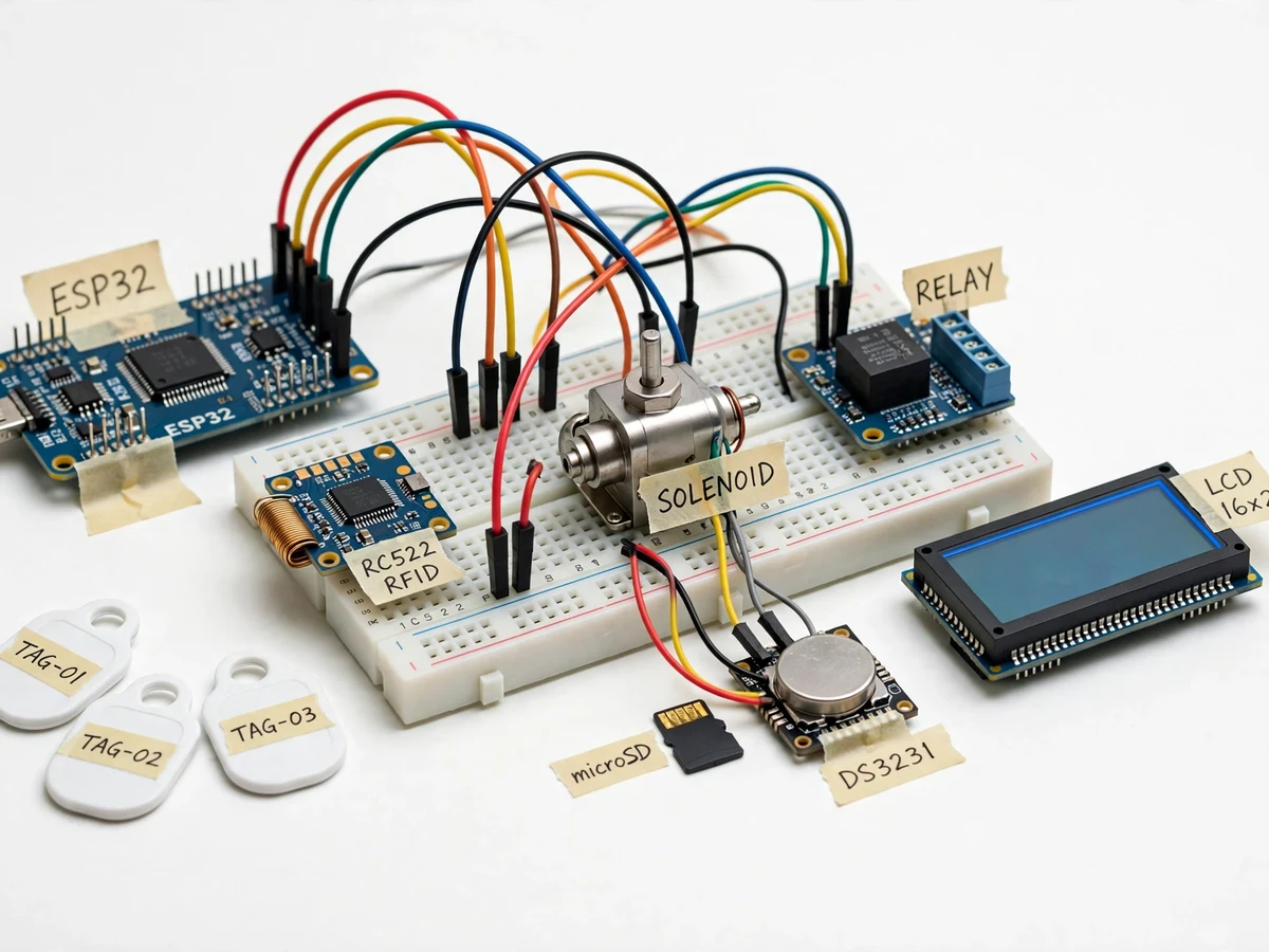
RFID access control is everywhere — office doors, hostels, labs — yet most students only ever see the finished reader on a wall, never the sensing, decision and actuation chain behind it. This project opens that box. A 13.56 MHz RC522 reader scans tags presented at the door; the ESP32 checks the UID against an enrolled list, and on a match it pulses a solenoid strike plate to unlock the door while recording the event (UID, granted/denied, date-time) to an SD card using a DS3231 real-time clock. Denied tags trigger a buzzer and a red LED; a tamper switch on the enclosure sounds a continuous alarm if the reader housing is forced open. The build teaches the full access-control loop: RF UID acquisition, whitelist management, timestamped logging, and safe driving of an inductive load with a relay and flyback diode.
How it works
- A tag is presented to the RC522 reader; the module returns the tag's UID to the ESP32 over SPI.
- The firmware compares the UID with the whitelist held in flash memory and reads the current date-time from the DS3231 RTC.
- On a match, the ESP32 energizes the relay for the configured unlock interval, pulsing the 12 V solenoid strike to release the door, and logs a GRANTED event to the SD card.
- On an unknown tag, access stays denied: the red LED flashes, the buzzer beeps, and a DENIED event is logged.
- Recent log entries can be scrolled on the LCD; the full log file is readable by removing the SD card.
- Holding the master tag for 3 seconds enters enroll mode, where new tags are added; a long hold deletes a tag. A tamper switch on the housing drives the continuous alarm until the reset key sequence is entered.
Tech stack:
- ESP32 development board (Wi-Fi capable, used here as the controller)
- RC522 13.56 MHz RFID reader module + keyfob/card tags
- 12 V solenoid door strike / latch
- Single-channel 5 V relay module with flyback diode
- DS3231 real-time clock module
- MicroSD card module (SPI logging)
- 16x2 character LCD
- Arduino IDE (C/C++ firmware)
| Parameter | Value |
|---|---|
| Controller | ESP32 dev board, SPI to RC522 and SD card, I2C to RTC/LCD |
| Reader | RC522, 13.56 MHz, typical read distance 3–5 cm (design target) |
| Lock actuator | 12 V DC solenoid strike, relay-pulsed, unlock interval configurable (design target 5 s default) |
| Logging | MicroSD card, CSV: UID, granted/denied, DS3231 date-time; LCD scroll of recent events |
| Enrollment | Master-tag mode: enroll new tags, delete tags, no re-flashing needed |
| Tamper sensing | Enclosure micro-switch → continuous buzzer alarm until key-sequence reset |
| Display | 16x2 LCD: LOCKED/UNLOCKED state, last UID, log count |
| Power | 12 V DC for solenoid; 5 V DC logic supply (USB or adapter) |
Project features
- [Contactless RFID authentication] RC522 13.56 MHz reader reads tag UIDs from a distance of approximately 3–5 cm; the UID is matched against an enrolled whitelist stored in the ESP32's flash.
- [Solenoid strike actuation] On an authorized tag, a relay pulses the solenoid door strike for a configurable interval (design target 5 s), then re-locks automatically.
- [Time-stamped access log] Every granted and denied attempt is written to a microSD card with UID, result and DS3231 date-time; recent events scroll on the LCD.
- [Enroll/delete from the panel] Master-tag mode enrolls new tags or wipes the whitelist without re-flashing, demonstrating real key-management behavior.
- [Tamper alarm] A micro-switch on the enclosure triggers a continuous buzzer alarm if the reader housing is opened, with a reset key sequence on the panel.
- [LCD status display] A 16x2 LCD shows LOCKED / UNLOCKED, last UID and log count, so the examiner can follow the demo live.
- [Inductive-load-safe driving] The solenoid is switched through a relay with a flyback diode and a separate 12 V supply, documenting how embedded boards safely drive inductive actuators.
What is included
- Working RFID door lock prototype (ESP32, RC522 reader, solenoid strike, relay, RTC, SD module, LCD, tamper switch)
- Complete firmware source code (UID scan, whitelist, logging, enroll mode, tamper alarm)
- Circuit and wiring documentation with relay/flyback safety notes
- Component list with ratings
- Tag enrollment and demo procedure guide
- Project report PDF (access-control background, RFID theory, methodology, test procedure)
- PPT presentation for final review
- Viva Q&A preparation document (RFID fundamentals, UID security limits, RTC logging)
- Setup and demonstration guide
Limitations & prerequisites
- UID-only RFID is identification, not strong authentication: UIDs can be cloned, so this is a demonstration of access-control concepts, not a security-certified lock.
- Read distance is limited to approximately 3–5 cm by the RC522 antenna; tags must be held close to the reader.
- The solenoid strike suits a demonstration door frame; it is not a replacement for a building's installed locking hardware.
- Log timestamps depend on the DS3231 battery-backed clock — the RTC battery must be fitted, or time resets on power loss.
- The SD log is plain CSV with no encryption; physical access to the card means access to the log.
Frequently Asked Questions
Which controller is used?
An ESP32 development board. It reads UIDs from the RC522 over SPI, checks the whitelist, timestamps events with the DS3231 RTC, drives the relay and LCD, and writes the log to SD.
How are tags enrolled?
Through master-tag mode: hold the master tag to enter enroll mode, present each new tag to add it, or delete one. No re-flashing is needed — key management happens on the panel.
Is UID-based RFID secure?
Not against a determined attacker — UIDs can be cloned with cheap tools. The listing is honest about this: it demonstrates the access-control loop (sense → decide → actuate → log), not a certified security product.
What does the access log contain?
Each line records the tag UID, GRANTED or DENIED, and the DS3231 date-time. Recent events scroll on the LCD; the full CSV is read from the SD card.
What power does it need?
12 V DC for the solenoid strike (switched through a relay with flyback protection) and 5 V DC for the ESP32 logic.
Is this project suitable for a final-year project?
Yes — for IoT and Embedded Systems programs. It combines RF sensing, real-time logging, electromechanical actuation and honest discussion of RFID security limits, all strong viva material. Suitable for B.E./B.Tech final-year projects in IoT and Embedded Systems.
Components & software requirements
- ESP32 development board (Wi-Fi capable, used here as the controller)
- RC522 13.56 MHz RFID reader module + keyfob/card tags
- 12 V solenoid door strike / latch
- Single-channel 5 V relay module with flyback diode
- DS3231 real-time clock module
- MicroSD card module (SPI logging)
- 16x2 character LCD
- Arduino IDE (C/C++ firmware)
Delivery information
Built-to-order project. Delivery timeline is shared after order confirmation based on current queue.
Support terms
Complete documentation, setup guide, and viva preparation included. Support for setup and explanation provided.