
More project photos (2)
The problem
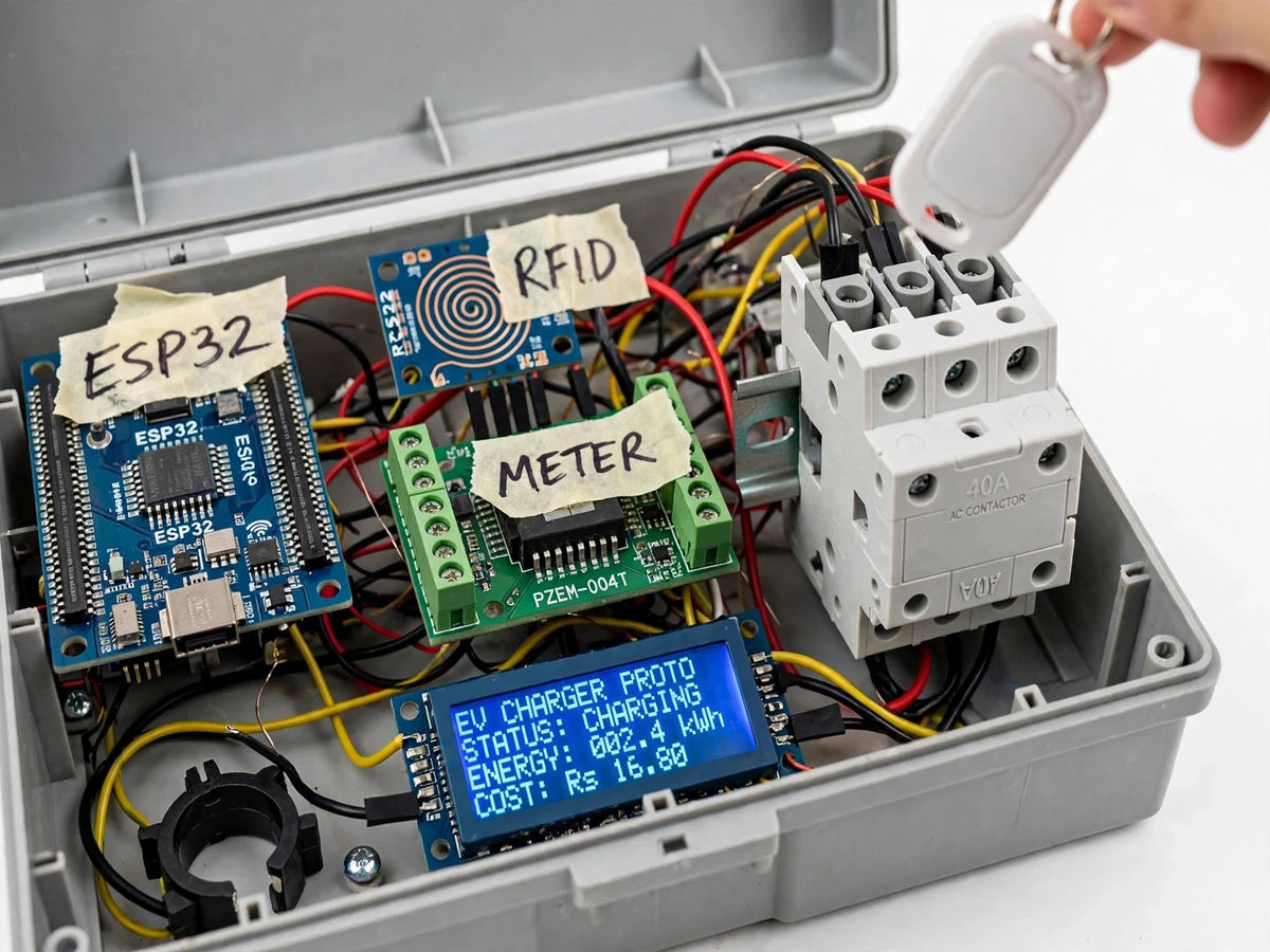
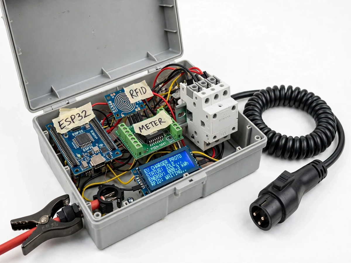
A shared home or apartment EV charger raises two practical questions: who is drawing the power, and how much of it? A plain wall socket cannot answer either — it has no user check, no metering and no way to stop the main breaker from tripping when the charger runs alongside the geyser and air conditioner. This project builds an AC EV charger control unit that answers both. An ESP32 controller reads a 13.56 MHz RFID tag through an RC522 reader before anything switches on, a PZEM-004T module measures voltage, current, power and cumulative energy for the session, and a 1 kHz pilot signal tells the vehicle its current limit in the J1772-style duty-cycle convention. Because a second current-transformer clamp watches the home mains incomer, the controller can throttle the vehicle in real time so the house and the charger together stay under the sanctioned load. The result is a working demonstration of authenticated access, energy billing and dynamic load sharing — the three systems every commercial smart charger is built on.
Taps the RFID tag to start the session and taps again to end it.
Follow the working sequence
How it works
- The vehicle plug connects, and the control pilot line voltage change tells the ESP32 that a vehicle is present and connected.
- The user taps an RFID tag on the RC522 reader; the firmware checks the UID against its authorized list and rejects unknown cards on the LCD.
- Once both the pilot handshake and RFID authentication pass, the ESP32 closes the 40 A contactor, energizing the charge socket.
- The ESP32 drives the 1 kHz pilot PWM with a duty cycle that encodes the vehicle's allowed current, and charging begins.
- The PZEM-004T continuously reports voltage, current, power and cumulative energy over TTL serial, while the CT clamp on the home incomer reports total household load.
- If house plus EV current would cross the sanctioned limit, the firmware lowers the pilot duty cycle and the vehicle throttles in real time.
- The 20×4 LCD shows session status, energy in kWh and running cost in rupees throughout; tapping the tag again ends the session, opens the contactor and freezes the final bill.
Tech stack:
- ESP32 dev module · Arduino framework
- RC522 RFID reader · 13.56 MHz
- PZEM-004T V3.0 energy meter module
- 40 A AC contactor · opto-isolated driver
- 20×4 LCD · I2C
- J1772-style 1 kHz pilot signalling
- Split-core CT clamp · mains incomer sensing
- Arduino IDE / PlatformIO · C++
| Parameter | Value |
|---|---|
| Controller | ESP32 dual-core 240 MHz, 3.3 V logic (datasheet value) |
| RFID reader | RC522, 13.56 MHz, read range approximately 3–5 cm (design target) |
| Energy meter | PZEM-004T V3.0, 100 A CT version |
| Meter voltage range | 80–260 VAC, 0.1 V resolution, 0.5% accuracy (datasheet value) |
| Meter current range | 0–100 A, 0.001 A resolution, 0.5% accuracy (datasheet value) |
| Meter energy range | 0–9999.99 kWh, 1 Wh resolution, 0.5% accuracy (datasheet value), resettable via software |
| Meter interface | TTL serial, 9600 baud, 8N1, Modbus-RTU (datasheet value) |
| Load switch | 40 A AC contactor with opto-isolated relay driver (datasheet value) |
| Pilot signal | 1 kHz PWM, duty cycle encodes current limit per J1772 pilot convention (design target) |
| Charging capacity | Up to 7.4 kW at 230 VAC / 32 A single phase (design target) |
| Home-load sensing | Split-core CT clamp on mains incomer (design target range 0–100 A) |
| Display | 20×4 character LCD over I2C (datasheet value) |
| Tariff | Configurable per-unit rate in ₹/kWh (firmware constant) |
| Enclosure | ABS control-unit box with cable glands (approximate) |
| Input supply | 230 VAC, 50 Hz, single phase (design target) |
Project features
- [RFID user authentication] The RC522 reader scans a 13.56 MHz tag and checks its UID against the authorized list stored in firmware. Charging can never start on an unknown card, so each session is tied to a known user.
- [J1772-style pilot signalling] The ESP32 generates a 1 kHz PWM pilot signal whose duty cycle encodes the vehicle's allowed current, following the J1772 pilot convention. The contactor closes only after the pilot handshake confirms a vehicle is connected.
- [PZEM-004T energy metering] The meter module reports mains voltage, current, active power and cumulative energy over TTL serial, with 0.5% measurement accuracy per its datasheet. Session cost is computed from cumulative kWh at the configured tariff.
- [Dynamic home-load throttling] A split-core CT clamp on the home mains incomer lets the controller sense total household load. If house plus EV current would exceed the sanctioned limit set in firmware, the pilot duty cycle is lowered and the vehicle throttles in real time.
- [40 A contactor load switching] The mains path is opened and closed by a 40 A AC contactor under ESP32 control, with the coil driven through an opto-isolated relay. Session start and stop are clean electrical events, not software abstractions.
- [20×4 LCD session display] The display shows session status, session energy in kWh and running cost in rupees, computed live from the configured per-unit tariff.
- [Configurable tariff and limits] The per-unit energy rate, sanctioned home load and pilot current range are firmware constants the student can adjust and defend in the viva.
- [Session reset and billing summary] The PZEM's cumulative energy is reset via software at each session start, and the final energy and cost freeze on the display when the session ends.
Implemented above. Optional customization and future scope (not in the base build):
- Optional: Wi-Fi session logging to a spreadsheet or local server.
- Optional: multiple-tariff time-of-day billing logic.
- Future scope: online payment or UPI settlement per RFID user.
- Future scope: OCPP-style remote management and a mobile app.
What is included
- Assembled control-unit prototype in an enclosure (ESP32, RC522, PZEM-004T, contactor, LCD, CT clamp, charge connector)
- Complete ESP32 firmware source (RFID auth, pilot PWM, metering, tariff billing, dynamic throttling)
- Wiring diagram and full component list with ratings
- Project report PDF (design, pilot-signal design, tariff math, safety notes)
- PPT presentation for final review
- Viva Q&A preparation document (RFID, pilot signalling, metering accuracy, load sharing)
- Demonstration guidance (RFID tap demo, LCD readings, pilot duty-change demo)
Limitations & prerequisites
- Academic prototype: no grid certification and no tested J1772 interoperability — the pilot follows the J1772 duty-cycle convention in firmware only.
- RFID UIDs are checked against a list in firmware with no card encryption, so it is an access list, not a secure payment system.
- PZEM accuracy (0.5% per datasheet) applies at the module; CT placement and mains wiring add their own error.
- Dynamic throttling only works if the CT clamp is installed on the true mains incomer; a mis-placed clamp breaks the limit math.
- Vehicle behaviour on pilot duty changes varies by model and is not verified across vehicles.
- All mains wiring and the contactor must be installed and first-tested under qualified supervision; demos run at limited current (design target 6–10 A) unless supervised.
- Single-phase AC only — three-phase charging is out of scope.
Frequently Asked Questions
Is this project suitable for a final-year project?
Yes — for Electrical, Electronics and IoT programs. It combines mains power switching, energy metering, RFID access control and firmware-based load management, giving examiners concrete hardware, calculations and a live demo to discuss.
Which controller is used and why?
An ESP32. It provides SPI for the RC522, a hardware UART for the PZEM-004T, PWM output for the 1 kHz pilot, and enough processing headroom for the tariff and throttling logic in one chip.
Does it need the internet to work?
No. Authentication, metering, pilot signalling, throttling and the LCD billing all run fully offline. Wi-Fi session logging is an optional customization, not required.
What supply and current can it handle?
The design target is 230 VAC single-phase with the contactor rated at 40 A and a charging design target of 7.4 kW (32 A). Demo sessions are run at a limited 6–10 A unless a supervisor approves more.
Is this a certified EV charger?
No. It is an academic prototype demonstrating authenticated, metered, load-aware charging. It carries no grid certification and no tested J1772 compliance, and mains work must be done under qualified supervision.
Can it bill different users separately?
Yes, per session. Each RFID UID starts its own session with its own energy and cost totals, shown on the LCD. Actual money collection or online payment is future scope.
Components & software requirements
- ESP32 dev module · Arduino framework
- RC522 RFID reader · 13.56 MHz
- PZEM-004T V3.0 energy meter module
- 40 A AC contactor · opto-isolated driver
- 20×4 LCD · I2C
- J1772-style 1 kHz pilot signalling
- Split-core CT clamp · mains incomer sensing
- Arduino IDE / PlatformIO · C++
Delivery information
Built-to-order project. Delivery timeline is shared after order confirmation based on current queue.
Support terms
Complete documentation, setup guide, and viva preparation included. Support for setup and explanation provided.
Download free synopsis (PDF)
Enter your name and email — the synopsis PDF downloads immediately. We may send occasional project updates; no spam, unsubscribe anytime.