
More project photos (2)
The problem
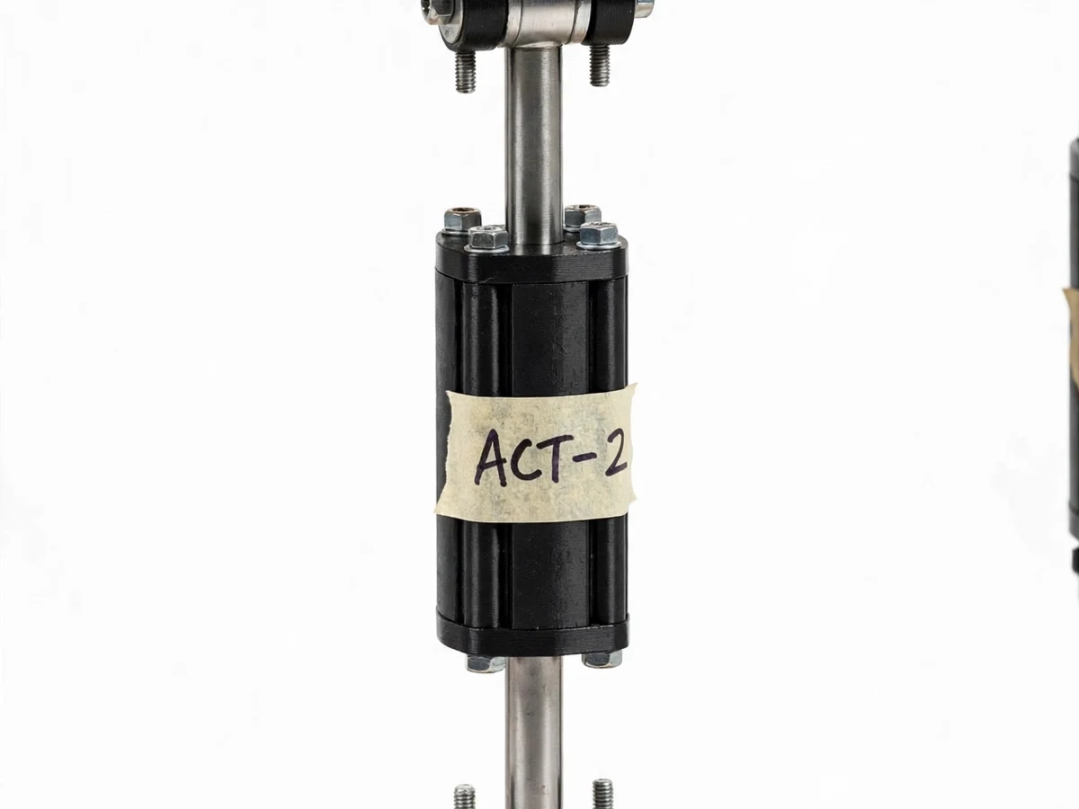
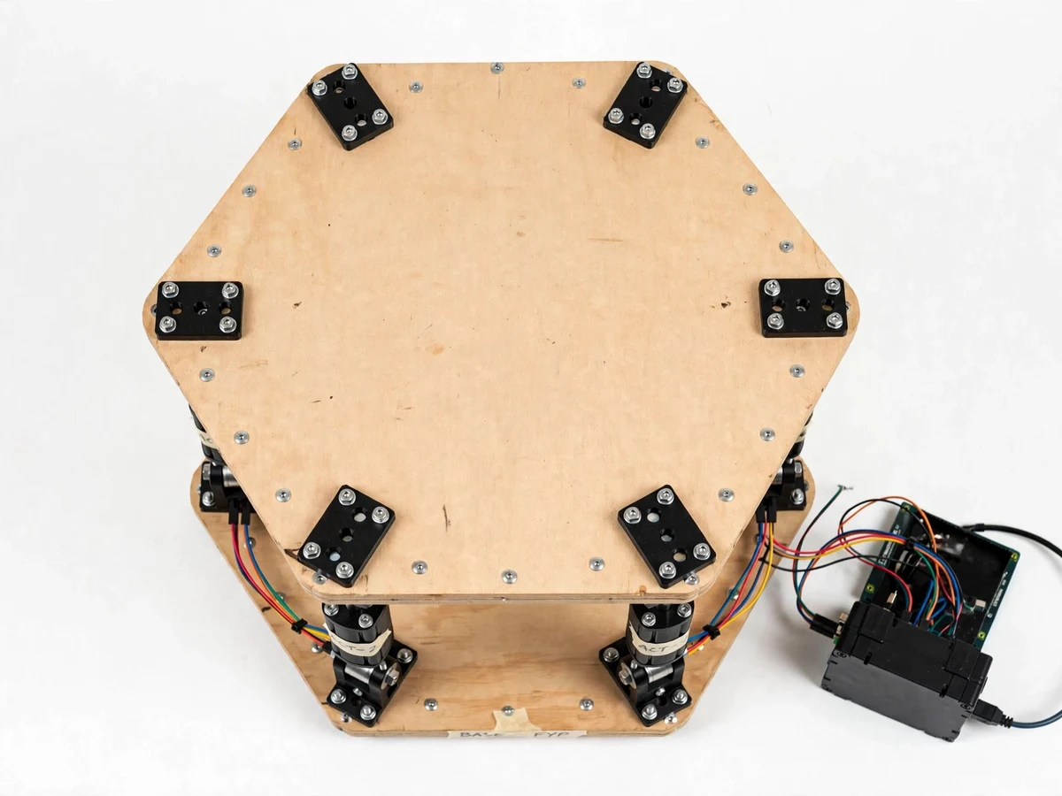
Most student robots are serial arms — one joint stacked on another. The Stewart platform is the opposite: a parallel robot where six actuators work together to position one plate, giving it six degrees of freedom (three translations, three rotations) with remarkable stiffness. It is the mechanism behind flight simulators, telescope mounts and precision vibration tables. The mathematics that makes it work — inverse kinematics, converting a desired platform pose into six actuator lengths — is genuinely instructive and very demonstrable: command a pitch angle and watch all six actuators move in concert. This project builds a tabletop Stewart platform with six small linear actuators, an Arduino Mega controller, and firmware the student writes around the inverse-kinematics equations, calibrated to their own build's geometry.
How it works
- The student measures the six base and six platform joint coordinates of their own build and enters them via the calibration routine.
- A desired platform pose (position + orientation) is specified — from a preset, a script, or the joystick.
- The inverse-kinematics function computes the required length of each of the six actuators from the pose and the calibrated geometry.
- The Arduino Mega converts each length to a servo/PWM command and drives all six actuators simultaneously.
- The top plate moves to the commanded pose; at approximately 20 Hz update rate the motion is smooth and continuous.
- Preset sequences chain poses over time — a tilt wave, a circular sway, a heave bounce — demonstrating the full motion envelope.
- Software travel limits clamp every command inside the safe actuator range, so no sequence can overdrive the mechanism.
Tech stack:
- Arduino Mega (kinematics controller)
- 6x linear actuators (servo-driven)
- Universal joint sets (12)
- Base + top plates (machined/plywood)
- Joystick input module
- Inverse-kinematics firmware (C++)
- Calibration routine
- 6 V high-current actuator supply
| Parameter | Value |
|---|---|
| Controller | Arduino Mega 2560 — datasheet |
| DOF | 6 (surge, sway, heave, roll, pitch, yaw) |
| Actuators | 6x servo-driven linear, approximately 100 mm stroke (prototype) |
| Joints | 12 universal joints (prototype) |
| Update rate | Approximately 20 Hz pose update (firmware, design) |
| Motion range | Pitch/roll approximately ±15°, heave approximately ±40 mm (expected) |
| Input | Joystick + preset sequences + serial commands (implemented) |
| Power | 6 V high-current actuator bus + logic supply (design) |
| Platform size | Approximately 40 cm across (prototype) |
Project features
- [Six-DOF parallel mechanism] Six linear actuators on universal joints connect base and top plates — the authentic Stewart (Gough-Stewart) geometry, not a simplified toy.
- [Inverse-kinematics firmware] The student implements the pose-to-actuator-length equations on the Arduino Mega, the mathematical heart of the project.
- [Programmable motion sequences] Pitch, roll, heave, yaw and combined motions scripted as timed sequences for demonstration.
- [Joystick live control] A joystick maps directly to platform attitude in real time, making the kinematics tangible during the demo.
- [Geometry calibration routine] Firmware includes a calibration procedure that measures the student's actual joint positions and feeds them into the kinematics.
- [Pose preset library] Level, tilt-wave, circular sway and vibration-demo presets show off the motion envelope.
- [Stall and limit protection] Software travel limits and current-aware stall handling protect the actuators from mechanical overdrive.
What is included
- Stewart platform (assembled: plates, 6 actuators, 12 universal joints)
- Arduino Mega controller (programmed with kinematics firmware)
- Complete firmware source code with inverse-kinematics implementation
- Geometry calibration procedure document
- Joystick control module
- Wiring diagram and mechanical assembly guide
- Motion-sequence scripting guide
- Project report PDF (background, parallel-robot kinematics, calibration, results)
- PPT presentation for final review
- Viva Q&A preparation document (inverse kinematics, DOF, calibration)
Limitations & prerequisites
- This is a tabletop demonstrator with hobby-grade actuators; it cannot carry human-scale loads or reproduce simulator-grade accelerations — the report states the scale honestly.
- Motion range is limited by the approximately 100 mm actuator stroke; extreme poses are software-clamped for safety.
- Hobby servos have backlash and limited precision, so pose repeatability is approximately ±2 mm (expected), documented honestly.
- The inverse kinematics assumes rigid links; frame flex under load is discussed as an error source in the report.
- Update rate of approximately 20 Hz suits smooth demo motions, not high-frequency vibration profiles.
- Calibration must be re-run if the mechanism is disassembled; the procedure document covers this buyer-run step.
Frequently Asked Questions
What is inverse kinematics and why does this project need it?
Forward kinematics asks "where is the plate given these actuator lengths" (hard for parallel robots). Inverse kinematics asks the useful question: "what actuator lengths put the plate in this pose" — and for the Stewart platform it has a clean geometric solution, which the firmware implements.
How is it different from a robot arm?
A serial arm stacks joints in a chain; errors accumulate and stiffness is low. The Stewart platform's six actuators work in parallel between two plates — stiffer, more precise, and the reason real flight simulators use this geometry.
What motions can it demonstrate?
All six degrees of freedom: pitch, roll and yaw rotations plus heave, surge and sway translations — individually via joystick or combined in scripted sequences like the tilt wave.
How accurate is the positioning?
Approximately ±2 mm repeatability is expected with hobby actuators; the report measures it on the student's own build and discusses backlash and frame flex as the limiting factors.
Do I need to understand the math to build it?
The report derives the inverse kinematics step by step and the firmware is commented around the equations — by the end, the student genuinely owns the mathematics, which is the project's main viva strength.
Is this project suitable for a final-year project?
Yes — for Mechanical, Electronics and Electrical programs. Parallel-robot kinematics is advanced, demonstrable, and rare among student projects. Suitable for B.E./B.Tech final-year projects in Mechanical, Electronics and Electrical.
Components & software requirements
- Arduino Mega (kinematics controller)
- 6x linear actuators (servo-driven)
- Universal joint sets (12)
- Base + top plates (machined/plywood)
- Joystick input module
- Inverse-kinematics firmware (C++)
- Calibration routine
- 6 V high-current actuator supply
Delivery information
Built-to-order project. Delivery timeline is shared after order confirmation based on current queue.
Support terms
Complete documentation, setup guide, and viva preparation included. Support for setup and explanation provided.