
More project photos (2)
The problem
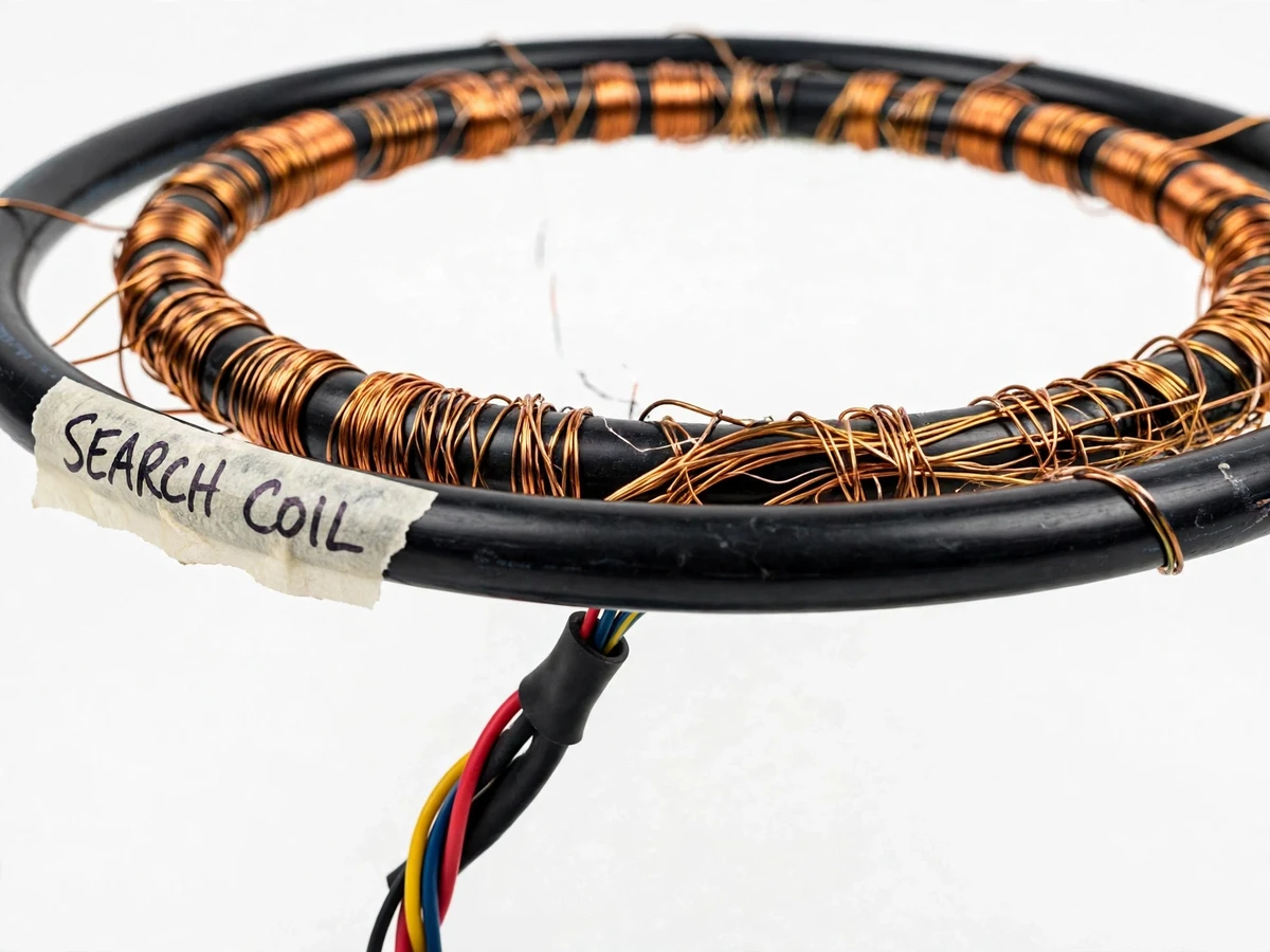
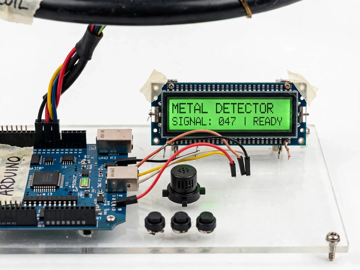
Most hobby metal detectors beep when anything metallic is near and say nothing about what it is or how deep it sits — fine for beachcombing, useless for learning. This project goes two levels deeper: the student winds the search coil themselves, builds the beat-frequency oscillator pair from discrete components, and uses the Arduino to measure the frequency shift, classify the target as ferrous or non-ferrous from the shift's direction, and display an indicative depth zone from the signal strength. Along the way the build touches LC resonance, electromagnetic induction, frequency measurement, sensor calibration and user-interface design — exactly the chain of reasoning an E&TC examiner probes in a viva. Because the firmware exposes the raw measured frequency on the LCD, the student can demonstrate the physics live: bring an iron nail close and the frequency falls; bring a copper coin and it rises; bury the coin deeper and the signal strength shrinks. Nothing about the detection is hidden inside a black box.
How it works
- The hand-wound search coil plus a fixed capacitor form an LC tank oscillating at roughly 90–150 kHz (design target), set by a 555-timer or Colpitts oscillator stage on the board.
- A second, identical reference oscillator runs freely at a nearby frequency; the two frequencies enter an XOR mixer, which outputs their difference (the beat) in the audible range, roughly 0–5 kHz (design target).
- When metal enters the coil's field, eddy currents and inductance changes shift the search oscillator's frequency, and the beat tone changes in response — the fundamental metal-detection effect.
- The Arduino samples the beat with a frequency-count routine and compares it to the stored baseline: a downward shift flags FERROUS, an upward shift flags NON-FER, with a deadband around zero to ignore noise.
- The size of the shift drives a signal-strength bar on the LCD; because strength decays with distance, the firmware maps it into an indicative depth zone calibrated from the buyer's own test burials.
- The buzzer pitch tracks the signal strength so the operator hears proximity without watching the screen, and the LCD shows the measured frequency for viva demonstrations.
- Calibration stores the baseline beat in clear air and the shift signatures of an iron nail and a copper coin as reference targets, so the discrimination thresholds are set on the actual hardware, not on assumed values.
Tech stack:
- Arduino Uno (ATmega328P, 16 MHz) firmware in C/C++
- Hand-wound search coil: enamelled copper wire on a PVC hoop
- LC tank resonance and beat-frequency oscillator theory
- 555 timer / transistor Colpitts oscillator design
- XOR-gate frequency mixing (74HC86)
- Frequency counting and baseline-tracking algorithms
- 16×2 character LCD interfacing
- Piezo buzzer tone generation
| Parameter | Value |
|---|---|
| Controller | Arduino Uno, ATmega328P at 16 MHz (datasheet value) |
| Search coil | ~200 mm diameter hoop, approximately 35 turns of 26 AWG enamelled copper wire (design target) |
| Search oscillator | LC tank, 90–150 kHz (design target), 555/Colpitts stage |
| Reference oscillator | Matched LC oscillator with trimmer capacitor (design target) |
| Beat output | 0–5 kHz audible difference tone (design target) |
| Detection depth | 15–20 cm for a coin-sized target in air (design target; measured by buyer during calibration) |
| Discrimination | FERROUS / NON-FER from shift direction (indicative, buyer-calibrated) |
| Display | 16×2 character LCD: frequency, shift sign, signal bar, depth zone, READY state |
| Audio | Piezo buzzer, pitch rises with signal strength (design target) |
| Controls | CAL push-button, discrimination-sensitivity trimmer |
| Power | 9 V battery or USB 5 V supply; ~50–80 mA draw (approximate) |
| Build form | Control box with coil on a detachable shaft (design target) |
Project features
- [Hand-wound search coil] A ~200 mm hoop wound with roughly 35 turns of 26 AWG enamelled copper wire (design target) forms the search-coil inductor — the student winds and fixes the coil themselves, and the report shows how turn count and diameter set the base frequency.
- [Beat-frequency oscillator pair] The search coil LC tank oscillates against a matched reference oscillator; a mixer (74HC86 XOR gate) produces an audible beat that rises as metal approaches the coil.
- [Ferrous vs non-ferrous discrimination] The Arduino reads the direction of the frequency shift: ferrous targets (iron, steel) increase inductance and push the frequency down, non-ferrous targets (copper, aluminium) induce eddy currents and push it up — displayed as FERROUS / NON-FER on the LCD.
- [Indicative depth readout] Signal strength falls as the target gets deeper, so the firmware maps the measured shift into a depth zone (SURFACE / SHALLOW / DEEP) on the LCD — indicative, not a ruler, and calibrated against the buyer's own buried-target tests.
- [Signal-strength LCD bar graph] A 16×2 display shows the measured frequency, shift direction, signal bar and depth zone at a glance, plus a READY indicator after calibration.
- [Pitch-rising audio feedback] A piezo buzzer whose pitch climbs with signal strength gives hands-free proximity cues, the same way commercial detectors work.
- [One-button calibration routine] Holding the CAL button in a clear area zeroes the baseline against local soil and temperature, and the buyer-run procedure stores ferrous/non-ferrous signatures from known test targets.
What is included
- Working metal detector prototype: wound search coil, oscillator board, Arduino control unit, LCD and buzzer
- Coil-winding and assembly guide with turn-count and frequency-setting notes
- Buyer-run calibration procedure: baseline zeroing, ferrous/non-ferrous signature recording, depth-zone mapping with buried test targets
- Arduino firmware source with frequency-count and discrimination logic
- Circuit schematic and wiring diagram of the oscillator and control stages
- Project report PDF (BFO theory, LC design, build log, calibration results template)
- PPT presentation for final review
- Viva Q&A preparation document (induction, eddy currents, LC resonance, beat frequency, discrimination limits)
Limitations & prerequisites
- All depth and frequency figures are design targets until the buyer measures them on their own build — the calibration procedure exists precisely so claimed numbers are verified, never assumed.
- Discrimination is indicative, not laboratory analysis: soil mineralization, target orientation, size and burial angle all move the reading; it classifies ferrous vs non-ferrous tendency on test targets, not alloy composition.
- The depth readout is an indicative zone (SURFACE / SHALLOW / DEEP) derived from signal strength — not a calibrated centimetre ruler — and it must be re-mapped for the local soil after calibration.
- Detection depth in mineralized or wet soil will be less than the in-air design target; ground mineralization raises the noise floor the beat measurement sits on.
- The coil is hand-wound by design, so its inductance varies slightly between builds; the trimmer and calibration routine exist to absorb that variation, and skipping calibration gives noisy results.
- Very small targets (below ~1 cm) or deeply corroded thin objects may not shift the frequency enough to cross the noise deadband.
- This is an educational demonstration build for study and viva purposes, not a survey-grade or security-grade detector.
Frequently Asked Questions
How does the detector tell ferrous from non-ferrous metal?
Ferrous metals raise the coil's inductance, which lowers the search oscillator's frequency; non-ferrous metals like copper and aluminium generate eddy currents that push the frequency up. The Arduino measures the shift direction against a calibrated baseline and displays FERROUS or NON-FER on the LCD — demonstrated live with an iron nail versus a copper coin.
Is the depth indication really accurate?
It is indicative, not a ruler. Signal strength falls with distance, so the firmware maps it to SURFACE / SHALLOW / DEEP zones — but the zones are only meaningful after the buyer runs the calibration procedure with known targets buried at measured depths in their own soil. The report template has a table for recording those real measurements.
Why do I have to calibrate it myself?
Because the search coil is hand-wound, every build has a slightly different inductance and base frequency, and local soil mineralization shifts the baseline too. The one-button CAL routine zeroes the detector against its actual environment in seconds, and the signature-recording step teaches how real instruments are commissioned — it is a viva strength, not a weakness.
What can I actually detect with it?
The design target is coin-sized objects (roughly 2–3 cm) down to about 15–20 cm in air. In practice the buyer verifies this with test targets: an iron nail, a copper coin and aluminium foil, at measured depths. Very small fragments and deeply corroded thin pieces may stay below the noise deadband.
Can it find gold or silver?
It responds to the conductivity and inductance signature of any metal, and gold and silver are non-ferrous conductors, so they register on the NON-FER side. But it cannot identify a specific alloy or prove a target is precious metal — that is beyond any student-grade BFO detector, and the report states this limit explicitly.
Is this project suitable for a final-year project?
Yes — for Electronics, E&TC and Instrumentation programs. It demonstrates LC resonance, electromagnetic induction, oscillator design, frequency measurement, sensor calibration and an Arduino-based instrument UI in one build, with real measurable phenomena the student can demonstrate and defend in a viva.
Components & software requirements
- Arduino Uno (ATmega328P, 16 MHz) firmware in C/C++
- Hand-wound search coil: enamelled copper wire on a PVC hoop
- LC tank resonance and beat-frequency oscillator theory
- 555 timer / transistor Colpitts oscillator design
- XOR-gate frequency mixing (74HC86)
- Frequency counting and baseline-tracking algorithms
- 16×2 character LCD interfacing
- Piezo buzzer tone generation
Delivery information
Built-to-order project. Delivery timeline is shared after order confirmation based on current queue.
Support terms
Complete documentation, setup guide, and viva preparation included. Support for setup and explanation provided.
Download free synopsis (PDF)
Enter your name and email — the synopsis PDF downloads immediately. We may send occasional project updates; no spam, unsubscribe anytime.