
More project photos (2)
The problem
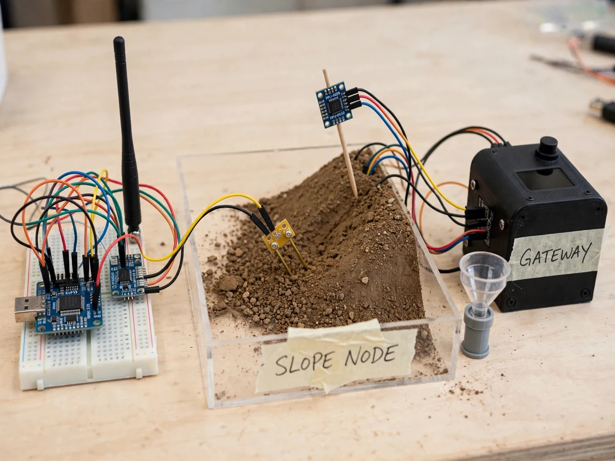
A hillside slope rarely fails without earlier signs: the ground tilts by small amounts, soil holds more water after sustained rain, and pore pressure builds before material starts to move. Watching those signs by eye is unreliable because the changes are slow, the slope may be far from any building, and the most dangerous period is during heavy rain when nobody should be standing near it. This project builds a slope node that measures tilt, soil moisture and rainfall together, judges them against combined thresholds, and radios a warning to a gateway placed at a safer distance. The gateway shows the warning level on an OLED and a local dashboard, and sounds a buzzer at the highest level, so the behaviour of a multi-factor warning chain can be studied and demonstrated on a tabletop slope model.
How it works
- The slope node reads the MPU6050 over I2C and computes tilt from the accelerometer axes, compares it with the baseline angle stored at setup, and records the tilt change for the current cycle.
- The capacitive soil-moisture probe is read on an analog input and mapped to a moisture percentage using the dry-soil and wet-soil calibration values stored in firmware, while bucket tips from the rain gauge are counted on an interrupt pin.
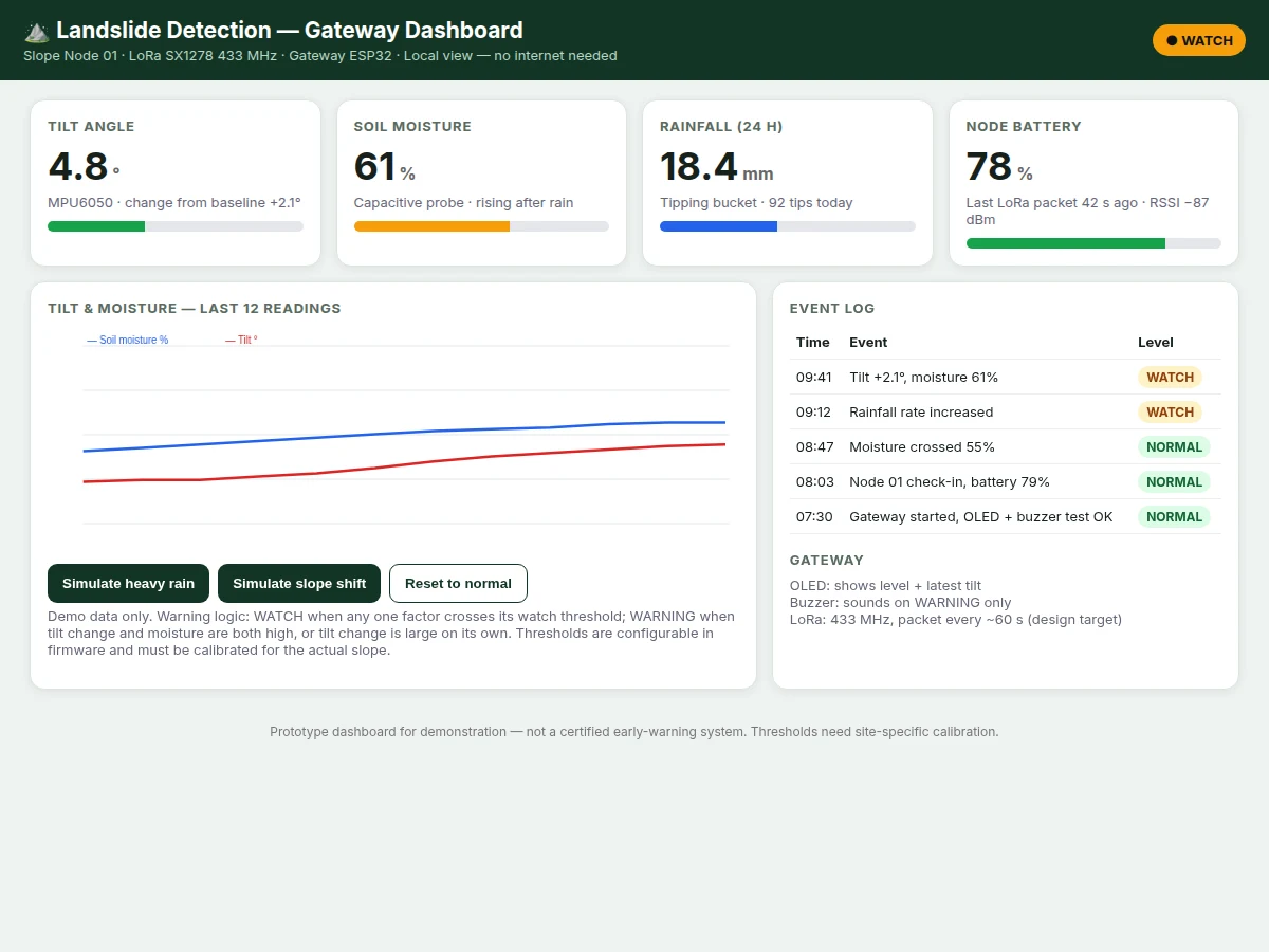
- The node ESP32 combines tilt change, moisture and rainfall into a warning level: NORMAL when all factors sit below watch thresholds, WATCH when any one factor crosses its watch level, and WARNING when tilt change is large or tilt and moisture are high together.
- The node packs tilt, moisture, rainfall, warning level and battery state into a short packet and transmits it with the SX1278 LoRa module at 433 MHz at the configured reporting interval, with alert packets sent immediately on a level change.
- The gateway ESP32 receives the LoRa packet, updates the OLED with the warning level and latest tilt value, and switches the buzzer on only when the level is WARNING.
- The gateway serves the local dashboard with the newest readings and appends every level change to the event log with its values, so a rain-and-tilt demonstration on the slope model can be followed from first WATCH to WARNING.
Tech stack:
- ESP32 development boards (node and gateway)
- MPU6050 6-axis IMU · I2C tilt sensing
- Capacitive soil-moisture sensor v1.2 class
- SX1278 LoRa module · 433 MHz
- Tipping-bucket rain gauge · funnel type
- SSD1306 OLED display · buzzer
- Arduino IDE (C/C++ firmware)
- HTML · CSS · JavaScript dashboard
| Parameter | Value |
|---|---|
| Controllers | 2 units of ESP32 development board — node and gateway (implemented) |
| Tilt sensor | MPU6050 6-axis IMU, accelerometer and gyroscope (datasheet) |
| Accelerometer range | ±2 g to ±16 g selectable ranges (datasheet) |
| Gyroscope range | ±250 °/s to ±2000 °/s selectable ranges (datasheet) |
| Soil sensor | Capacitive soil-moisture sensor, v1.2 class, analog output (datasheet class) |
| LoRa module | SX1278, 433 MHz band as configured (implemented) |
| LoRa link range | Approximately 1 km to 3 km line-of-sight (design target, terrain-dependent) |
| Rain gauge | Tipping-bucket type, approximately 0.2 mm per tip (typical, design target) |
| Reporting interval | Approximately every 60 s (design target, firmware-configurable) |
| Warning levels | NORMAL, WATCH, WARNING — 3 levels (implemented) |
| Gateway display | SSD1306 OLED, 128 × 64 pixels (datasheet) |
| Node supply | 5 V DC regulated adapter or battery pack (design target) |
| Dashboard | Local web dashboard — tilt, moisture, rainfall, battery, event log (implemented) |
Project features
- [Tilt sensing with MPU6050] An MPU6050 6-axis IMU (datasheet) mounted on a stake in the slope model reports tilt change from a stored baseline, so slow creep and sudden shifts are both visible as angle changes rather than raw acceleration values alone.
- [Capacitive soil-moisture sensing] A capacitive soil-moisture probe (v1.2 class) pushed into the slope soil reports moisture as a percentage after dry/wet calibration; the capacitive design avoids the exposed-electrode corrosion that shortens resistive probe life.
- [Rainfall counting with tipping bucket] A small funnel and tipping-bucket gauge counts bucket tips at the node, converting tips into an approximate rainfall total so moisture and tilt readings can be judged against how much rain actually fell.
- [Combined warning-level logic] Firmware classifies conditions as NORMAL, WATCH or WARNING (implemented) using tilt change, moisture level and rainfall together — a single high reading raises WATCH, while combined or large changes raise WARNING, reducing single-sensor false alarms.
- [LoRa warning alerts] An SX1278 LoRa module at 433 MHz (implemented) carries sensor packets and alert events from the slope node to the gateway without Wi-Fi or mobile coverage at the slope itself.
- [Gateway OLED and buzzer] The gateway ESP32 shows the current warning level and latest tilt on a small OLED, and drives a buzzer only at WARNING level (implemented), so the alert is audible in a room without watching a screen.
- [Local web dashboard] A dashboard served by the gateway shows live tilt, moisture, rainfall, node battery, the current warning level and an event log (implemented), giving one screen for demonstration and viva walkthroughs.
- [Configurable thresholds] Tilt, moisture and rainfall thresholds, the baseline angle and the reporting interval are firmware parameters (configurable in code); extra slope nodes and a GSM uplink at the gateway are optional customisations, not part of the base build.
What is included
- Working slope-node prototype (ESP32, MPU6050 on stake, capacitive moisture probe, tipping-bucket rain gauge, SX1278 with antenna, soil slope model tray)
- Working gateway unit (ESP32, SX1278 with antenna, SSD1306 OLED, buzzer, enclosure)
- Controller firmware / source code for node and gateway with warning-level logic and LoRa packet code
- Dashboard demo (single-file web app) showing tilt, moisture, rainfall, battery, warning level and event log
- Circuit diagrams, wiring documentation and component list for both units
- Calibration and threshold setup instructions (baseline angle, dry/wet moisture points)
- Project report PDF (background, sensor theory, warning-logic design, methodology)
- Project abstract PDF
- PPT presentation for final review
- Viva Q&A preparation document (IMU tilt maths, LoRa link budget basics, threshold design, false-alarm trade-offs)
Limitations & prerequisites
- Prototype scale: sensing is demonstrated on a tabletop soil slope model in a tray; behaviour on a real hillside with deep soil movement, rock and vegetation cannot be inferred from the model alone.
- Thresholds need site-specific calibration: a tilt or moisture value that signals risk on one slope is normal on another, so the shipped thresholds are demonstration values that must be retuned and observed over time for any real slope.
- LoRa range is terrain-dependent: the line-of-sight design target falls sharply with ridges, dense buildings and foliage between node and gateway, and antenna placement matters as much as the module itself.
- Soil-moisture percentage is a relative calibrated reading from one probe at one depth; it does not measure pore-water pressure and does not represent moisture deeper in the slope.
- False alarms are possible: animal disturbance, a knocked stake, drying cracks or a blocked rain funnel can move a reading, and the combined-level logic reduces but cannot remove that risk.
- The tipping-bucket figure of approximately 0.2 mm per tip (typical, design target) varies with funnel area and bucket adjustment, and very heavy rain can undercount while the bucket is mid-tip.
- Not a certified or geological early-warning system: there is no geotechnical validation, no authority alerting link and no safety certification — the build is an academic demonstration of the sensing and warning chain.
Frequently Asked Questions
Is this project suitable for a final-year project?
Yes — Electronics, IoT and Embedded Systems programmes can carry this build well. It demonstrates IMU tilt measurement, analog sensor calibration, interrupt counting, threshold decision logic, LoRa communication and a gateway dashboard in one chain, so each viva question can be answered from a part of the system that was actually built and tested on the slope model.
Why use tilt, moisture and rainfall together instead of one sensor?
A single sensor misleads easily: soil can be wet without moving, and a stake can tilt because it was knocked. Judging tilt change alongside moisture and rainfall gives context — movement after sustained rain and rising moisture is treated more seriously than any one reading alone, which is why the warning logic combines all three factors.
Which controller and radio are used, and why LoRa?
Both units use ESP32 boards. The radio is an SX1278 LoRa module working at 433 MHz as configured for this build. LoRa suits a slope node because packets are short, power stays modest, and the link works without Wi-Fi or mobile coverage at the slope, with range that depends strongly on terrain and antenna placement.
Does the system need internet to raise an alert?
No. Sensing, warning-level decisions, LoRa transmission, the OLED display, the buzzer and the local dashboard all run between the node and gateway without internet. Internet would only be needed for optional additions such as cloud logging or phone notifications from the gateway, which are customisations outside the base build described here.
How are the warning thresholds set?
At setup the node stores a baseline tilt angle on the undisturbed slope and dry/wet calibration points for the moisture probe. Watch and warning thresholds for tilt change, moisture and rainfall are firmware values chosen around those baselines. On a different slope the same procedure is repeated, because thresholds copied from another site have little meaning.
Can more slope nodes be added later?
Yes, as a customisation. The packet carries a node identity, so a gateway can distinguish packets from additional nodes placed on other faces of a slope. Each added node needs its own baseline and calibration, and the dashboard layout needs extending to show each node separately rather than mixing their readings together.
Components & software requirements
- ESP32 development boards (node and gateway)
- MPU6050 6-axis IMU · I2C tilt sensing
- Capacitive soil-moisture sensor v1.2 class
- SX1278 LoRa module · 433 MHz
- Tipping-bucket rain gauge · funnel type
- SSD1306 OLED display · buzzer
- Arduino IDE (C/C++ firmware)
- HTML · CSS · JavaScript dashboard
Delivery information
Built-to-order project. Delivery timeline is shared after order confirmation based on current queue.
Support terms
Complete documentation, setup guide, and viva preparation included. Support for setup and explanation provided.
Download free synopsis (PDF)
Enter your name and email — the synopsis PDF downloads immediately. We may send occasional project updates; no spam, unsubscribe anytime.