
More project photos (2)
The problem
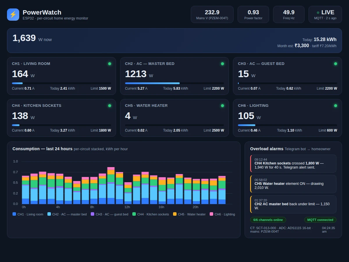
A single whole-house meter tells you how much electricity your home uses, but not where it goes. This project builds a per-circuit energy monitoring system that answers exactly that question: six clamp-on SCT-013-000 current transformers, one on each MCB outgoing wire, feed an ESP32 through ADS1115 16-bit ADCs, and a PZEM-004T module on the mains incomer supplies the voltage and power-factor reference. The ESP32 computes per-circuit RMS current and apparent power, publishes the readings over MQTT, and a cloud dashboard shows live per-circuit watts, a 24-hour consumption chart, daily kWh per circuit and a monthly cost estimate at a configurable tariff. Each circuit gets its own overload limit, and a sustained crossing sends a Telegram alert to the homeowner. The build is honest about its metrology: per-circuit readings are apparent power (mains voltage times measured RMS current), with true voltage, power factor and frequency coming from the PZEM-004T reference.
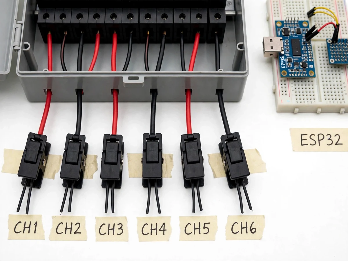
Six SCT-013-000 clamps on the MCB outgoing wires, each with an 18 ohm burden resistor.
Follow the working sequence
How it works
- Each SCT-013-000 clamp converts its circuit's AC current to a 0–50 mA secondary current, and the 18 Ω external burden resistor turns that into a small AC voltage centered on a 1.65 V bias rail.
- Two ADS1115 ADCs digitize the six channels at 16-bit resolution over I2C, giving the ESP32 clean samples the internal ADC could not deliver reliably.
- The ESP32 firmware samples each channel continuously and computes true RMS current over a 1-second window (50 mains cycles), rejecting DC offset in software.
- The PZEM-004T module on the mains incomer reports voltage, power factor, frequency and total active power over TTL serial every second.
- Per-circuit apparent power is calculated as measured mains Vrms × channel Irms; totals are cross-checked against the PZEM's whole-house reading.
- Every 2 seconds the ESP32 publishes a JSON payload (per-circuit watts, amps, kWh-so-far, mains V/PF/frequency) to an MQTT broker over Wi-Fi.
- The dashboard subscribes to the feed, updates the live cards and 24-hour chart, accumulates kWh, and evaluates each channel's overload limit; sustained crossings fire the Telegram bot.
Tech stack:
- ESP32 DevKit (Wi-Fi microcontroller)
- SCT-013-000 split-core CT, 100 A / 50 mA
- ADS1115 16-bit ADC × 2 (I2C)
- PZEM-004T energy meter module
- MQTT (Mosquitto broker)
- HTML/CSS/JavaScript dashboard
- Telegram Bot API (alerts)
- Arduino framework, EmonLib-style RMS math
| Parameter | Value |
|---|---|
| CT rating | 0–100 A AC per circuit (datasheet) |
| CT output | 0–50 mA AC, external burden required (datasheet) |
| CT turns ratio | 1:1800 (datasheet) |
| CT accuracy | ±1% (datasheet), 50 Hz–1 kHz |
| Burden resistor | 18 Ω, 1% metal film (design value, per OpenEnergyMonitor) |
| Channels | 6 single-ended CT channels (design value) |
| ADC resolution | 16-bit, 860 SPS maximum (datasheet) |
| Current resolution | Approximately 14 mA per LSB at unity gain (design calculation) |
| RMS window | 1 second, 50 mains cycles (design value) |
| Mains voltage reference | 80–260 V AC (PZEM-004T datasheet) |
| Mains frequency | 45–65 Hz (PZEM-004T datasheet) |
| Per-circuit power | Apparent power, Vrms × Irms (design value) |
| Dashboard refresh | 2 seconds (design value) |
| Alarm dispatch | Telegram within seconds of a sustained crossing (expected) |
| Supply | 5 V DC, 2 A USB adapter (design value) |
| Connectivity | 2.4 GHz Wi-Fi, MQTT (design value) |
Project features
- [Six per-circuit CT channels] One SCT-013-000 clamp on each MCB outgoing wire, each with its own 18 Ω external burden resistor converting the 0–50 mA CT output to a measurable voltage.
- [16-bit acquisition with ADS1115] Two ADS1115 ADCs (I2C addresses 0x48 and 0x49) give six calibrated 16-bit channels; the design avoids the ESP32's internal ADC, whose non-linearity near the rails and Wi-Fi conflicts make it a poor fit for multi-channel metering.
- [PZEM-004T mains reference] A PZEM-004T on the incomer measures true mains voltage (80–260 V AC), power factor and frequency over TTL serial, so apparent power is computed against a real voltage, not an assumed 230 V.
- [Live MQTT dashboard] The ESP32 publishes per-circuit watts, amps, daily kWh and mains readings every 2 seconds; the dashboard renders live cards, a stacked 24-hour consumption chart and channel health status.
- [Per-circuit overload alarms] Each channel has a configurable watt limit; a sustained crossing sends a Telegram message identifying the circuit, the peak value and the duration.
- [Energy accounting and cost estimate] Daily and monthly kWh per circuit with a monthly cost estimate at a user-set ₹/kWh tariff, so the homeowner sees which circuit drives the bill.
- [Guided calibration routine] A dashboard calibration flow lets the buyer trim each channel against a known load or reference meter, correcting burden-resistor and CT tolerance.
What is included
- Sensing hardware: 6 × SCT-013-000 clamps, 2 × ADS1115 modules, PZEM-004T with CT, ESP32 DevKit, burden-resistor signal boards, wiring
- ESP32 firmware (RMS computation, PZEM polling, MQTT publish, calibration mode, alarm logic)
- Cloud dashboard (live per-circuit cards, 24 h chart, kWh accounting, cost estimate, alarm log, calibration flow)
- MQTT broker configuration and Telegram bot setup guide
- Wiring diagram, MCB-panel installation guide and safety notes
- Calibration procedure against a reference load
- Project report PDF (background, CT/ADC theory, design calculations, methodology)
- PPT presentation for final review
- Viva Q&A preparation document (CT burden, RMS sampling, apparent vs real power, MQTT)
Limitations & prerequisites
- Per-circuit readings are apparent power (mains Vrms × measured Irms); per-circuit real power would need per-circuit phase measurement, which is not implemented — the mains power factor from the PZEM-004T is the only phase reference.
- End-to-end accuracy is approximately ±3% after calibration against a reference meter (expected); the CT itself is ±1% (datasheet) but burden tolerance, bias drift and noise add error, especially below 100 mA primary (design note).
- CTs measure AC only — they cannot detect DC leakage or DC-side consumption.
- Mains-voltage work must be done by a qualified person with the supply isolated; this is a teaching prototype, not a certified meter, and its readings are not valid for billing disputes.
- The cloud dashboard, cost estimates and Telegram alerts need 2.4 GHz Wi-Fi and internet; without them the unit logs locally only (design value).
- Tariff structures with time-of-day slabs are not modeled — the cost estimate uses a single flat ₹/kWh rate (design value).
Frequently Asked Questions
Why are there two ADS1115 ADCs instead of using the ESP32's own ADC?
The ADS1115 gives 16-bit resolution with a programmable gain amplifier and clean I2C interfacing. The ESP32's internal ADC is 12-bit, non-linear near the supply rails, and its ADC2 block conflicts with Wi-Fi — three properties that make it unreliable for six metering channels. Two ADS1115s at I2C addresses 0x48 and 0x49 provide the six channels this design needs.
Does the SCT-013-000 need a burden resistor?
Yes. The -000 variant outputs a 0–50 mA current signal with no internal burden (datasheet). This build uses an 18 Ω external burden resistor per channel, which converts full-scale 100 A primary current into roughly 1.27 V peak across the resistor — safely inside the ADC range on a 1.65 V bias.
Is the per-circuit power real power or apparent power?
Apparent power. Each channel measures RMS current and multiplies it by the mains RMS voltage from the PZEM-004T. Without per-circuit phase measurement there is no per-circuit power factor, so heavily reactive loads will read slightly high. The PZEM-004T's whole-house real power is shown alongside for comparison.
Can this be used for tenant submetering or billing?
No. It is a teaching and awareness prototype, not a certified meter. Use it to find which circuit drives the bill, then verify with a calibrated instrument before any money changes hands.
How is it calibrated?
The dashboard has a calibration flow: switch on a known resistive load (for example a 1 kW heater), let the channel settle, and trim that channel's gain constant until it reads correctly. Repeating this per channel removes burden-resistor and CT tolerance.
Is this project suitable for a final-year project?
Yes — for Electrical, Electronics and IoT programs. It demonstrates current-transformer theory, burden-resistor design, RMS signal processing, ADC selection trade-offs, MQTT telemetry and a real dashboard, with honest metrology in the report.
Components & software requirements
- ESP32 DevKit (Wi-Fi microcontroller)
- SCT-013-000 split-core CT, 100 A / 50 mA
- ADS1115 16-bit ADC × 2 (I2C)
- PZEM-004T energy meter module
- MQTT (Mosquitto broker)
- HTML/CSS/JavaScript dashboard
- Telegram Bot API (alerts)
- Arduino framework, EmonLib-style RMS math
Delivery information
Built-to-order project. Delivery timeline is shared after order confirmation based on current queue.
Support terms
Complete documentation, setup guide, and viva preparation included. Support for setup and explanation provided.
Download free synopsis (PDF)
Enter your name and email — the synopsis PDF downloads immediately. We may send occasional project updates; no spam, unsubscribe anytime.