
More project photos (2)
The problem
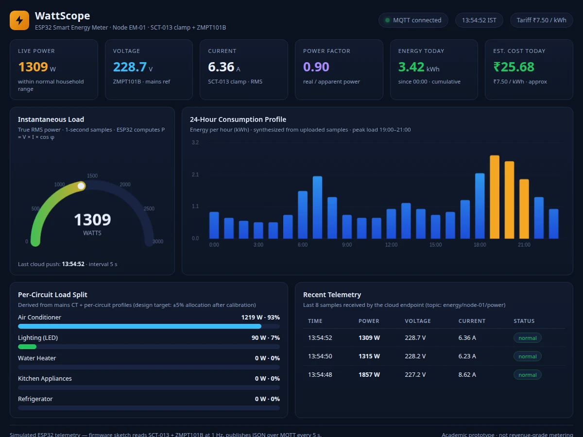
Most households get exactly one number from their electricity provider each month: total kilowatt-hours consumed. That single figure cannot say which appliance is the energy hog, whether the water heater is left on too long, or why the bill spiked last week. Utility smart meters aggregate everything into one opaque total, and installing per-appliance sub-meters means an electrician, rewiring and cost. The result is that energy waste hides in plain sight — families and small societies pay for consumption they cannot see, let alone manage. This project tackles that gap with a non-invasive approach: a split-core current-transformer clamp snaps around the incoming mains wire without cutting anything, a small voltage module senses line voltage, and an ESP32 computes real power locally and streams it to a cloud dashboard. The dashboard turns raw watts into understanding — a live power gauge, a 24-hour consumption profile, a per-circuit load split and a running cost estimate at the local tariff.
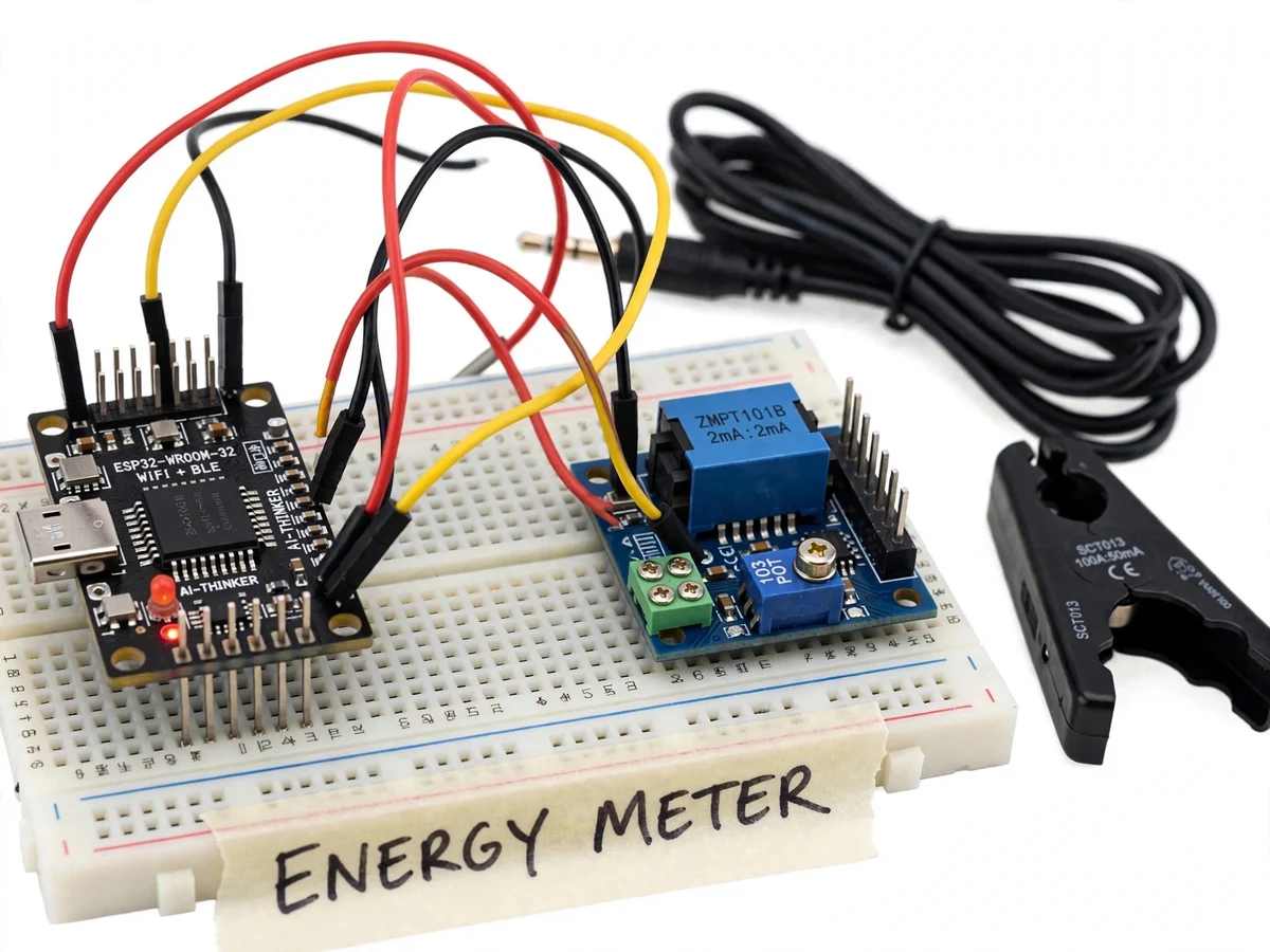
Split-core clamp around the phase conductor; a burden resistor converts secondary current to voltage.
Follow the working sequence
How it works
- The split-core SCT-013-000 clamp is snapped around the incoming phase conductor of the mains feed — the core opens and closes around the wire, so nothing is cut or spliced.
- The ZMPT101B module connects to the mains through its isolated terminal block and outputs a low-voltage AC waveform that tracks line voltage, with an on-module trim potentiometer for scaling.
- The CT's secondary current passes through a burden resistor sized per the SCT-013 datasheet, converting it to a voltage the ESP32's 12-bit ADC can sample.
- Firmware samples the current and voltage waveforms over several 50 Hz mains cycles, then computes RMS current, RMS voltage, real power, power factor and cumulative energy.
- Per-channel gain constants — set by the buyer against a reference meter using the included calibration procedure — correct the readings; constants are stored in ESP32 flash.
- Every 5 seconds the ESP32 publishes a JSON payload with V, I, P, PF and cumulative kWh over MQTT; the dashboard subscribes and renders the live gauge, 24-hour profile, per-circuit split and cost estimate.
Tech stack:
- ESP32-WROOM-32
- Arduino IDE · C++ firmware
- SCT-013-000 split-core CT clamp
- ZMPT101B voltage module
- Burden-resistor signal conditioning
- MQTT · PubSubClient · JSON telemetry
- HTML · CSS · JavaScript dashboard
- Mosquitto MQTT broker
| Parameter | Value |
|---|---|
| Controller | ESP32-WROOM-32, 240 MHz dual-core, 12-bit ADC |
| Current sensing | SCT-013-000 split-core CT, 0–100 A range (datasheet), 100 A : 50 mA |
| Voltage sensing | ZMPT101B module, up to 250 V AC (datasheet) |
| Electrical system | Single-phase 230 V AC, 50 Hz (design target) |
| Measurement | True-RMS voltage and current, real power, power factor, cumulative kWh (design target) |
| Accuracy | Approximately ±2–3% of reading vs a reference meter after buyer-run calibration (design target) |
| Telemetry | MQTT JSON payload every 5 s (configurable); dashboard refresh approximately 2 s |
| Dashboard | Live power gauge, 24-hour consumption profile, per-circuit load split, cost estimate — any modern browser |
| Node power | 5 V USB supply for the ESP32 node |
| Calibration | Gain constants set by the buyer against a reference meter; step-by-step procedure included |
Project features
- [Non-invasive CT current sensing] The split-core SCT-013-000 clamp snaps around the incoming phase conductor — no wire cutting, no electrician visit, no contact with live copper. Its 0–100 A datasheet range covers a typical household mains feed.
- [AC voltage reference measurement] A ZMPT101B module taps the mains through isolated terminals and outputs a scaled AC waveform, so the firmware measures real line voltage instead of assuming a fixed 230 V.
- [True-RMS firmware computation] The ESP32 samples the current and voltage waveforms over multiple mains cycles and computes RMS current, RMS voltage, real power and power factor in firmware — the same quantities a digital energy meter reports.
- [Wi-Fi/MQTT cloud telemetry] Every 5 seconds the node publishes a compact JSON payload (V, I, P, PF, cumulative kWh) to an MQTT broker, so the dashboard and any cloud logger stay in sync with the hardware.
- [Cloud load-profiling dashboard] A web dashboard renders the live power gauge, a 24-hour consumption profile chart, a scrolling recent-telemetry log and connection status — viewable from any browser, exactly as demonstrated in the working demo.
- [Per-circuit load split] The dashboard allocates the measured mains load across typical circuits (AC, water heater, lighting, kitchen, refrigerator) with labeled design-target allocation accuracy, turning one meter reading into actionable insight.
- [Running cost estimate] Energy consumed is multiplied by the configurable local tariff (default ₹7.50/kWh) to show an estimated daily cost, making the abstract unit of kWh concrete for the viewer.
- [High-load threshold flag] Samples above a configurable power threshold are flagged in the telemetry log, so unusual loads (e.g. two heavy appliances together) are visible at a glance.
What is included
- Assembled prototype: ESP32 board, SCT-013-000 clamp, ZMPT101B module on a wired base
- Complete Arduino C++ firmware with calibration constants in flash
- Cloud load-profiling dashboard (working demo instance plus full source)
- Wiring diagram and component list with exact part numbers
- Step-by-step calibration guide (reference-meter procedure the buyer performs)
- Project report PDF (AC sensing theory, conditioning design, firmware logic, results template)
- PPT presentation for final review
- Viva Q&A preparation document (CT theory, burden sizing, RMS vs average, MQTT)
Limitations & prerequisites
- Single-phase 230 V AC only — three-phase supply metering is out of scope for the base build (listed as an extension).
- Accuracy of approximately ±2–3% is a design target after buyer-run calibration, not a measured claim; the unit is an academic prototype, not a revenue-grade or utility-certified meter, and cannot be used for billing disputes.
- The CT introduces a small phase error that shifts power-factor readings at very low loads; firmware compensation is approximate.
- Wi-Fi is required for live dashboard and cloud logging; when the network drops, the node keeps accumulating kWh in flash but the dashboard freezes until reconnection.
- The ZMPT101B module's mains terminals carry live 230 V AC — wiring must be done with the supply isolated, and the prototype is not suitable for unsupervised beginners.
- The per-circuit load split is an allocation estimate derived from the mains reading, not per-circuit metering; its accuracy is a design target of approximately ±5% after calibration.
Frequently Asked Questions
Which sensors measure the current and voltage?
Current is measured by an SCT-013-000 split-core current transformer clamped around the phase conductor — it outputs a small current proportional to the mains current, converted to voltage by a burden resistor. Voltage is measured by a ZMPT101B module whose isolated transformer outputs a scaled AC waveform tracking the 230 V line. Both are industry-standard parts for DIY energy monitors.
Is this project suitable for a final-year project?
Yes — for IoT & Embedded, Electronics / E&TC and Electrical programs. It demonstrates AC sensing theory, analog signal conditioning, embedded firmware with real math (RMS, power factor), MQTT telemetry and a full cloud dashboard — a complete sense-to-cloud pipeline that examiners can test live.
Does installing the clamp need an electrician?
No. The split-core clamp opens on a hinge, snaps around the insulated phase conductor and closes again — no wire is cut, stripped or spliced. The ZMPT101B module does need a mains connection for voltage reference, which is done with the supply switched off and isolated, following the included wiring guide.
Can this replace my electricity board's meter?
No, and it should never be presented that way. Utility meters are certified and sealed; this is an academic prototype with a design-target accuracy of approximately ±2–3% after calibration. Its value is insight — seeing where energy goes in real time — not billing.
What happens if the Wi-Fi disconnects?
The dashboard stops updating because it receives data over MQTT, but the ESP32 keeps computing and accumulates energy in its flash memory. On reconnection it resumes publishing, so no consumption is lost from the cumulative counter — only the live view pauses.
Can it be extended to three-phase or solar monitoring?
Yes, as an optional customization: three-phase needs three CT clamps plus three voltage references (or a three-phase energy IC), and solar monitoring adds a DC-side sensor. These are developed as extensions based on requirements, feasibility and timeline. Suitable for B.E./B.Tech final-year projects in IoT & Embedded, Electronics / E&TC and Electrical.
Components & software requirements
- ESP32-WROOM-32
- Arduino IDE · C++ firmware
- SCT-013-000 split-core CT clamp
- ZMPT101B voltage module
- Burden-resistor signal conditioning
- MQTT · PubSubClient · JSON telemetry
- HTML · CSS · JavaScript dashboard
- Mosquitto MQTT broker
Delivery information
Built-to-order project. Delivery timeline is shared after order confirmation based on current queue.
Support terms
Complete documentation, setup guide, and viva preparation included. Support for setup and explanation provided.
Download free synopsis (PDF)
Enter your name and email — the synopsis PDF downloads immediately. We may send occasional project updates; no spam, unsubscribe anytime.