
More project photos (3)
The problem
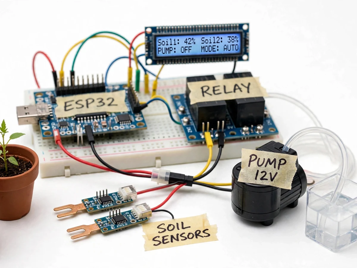
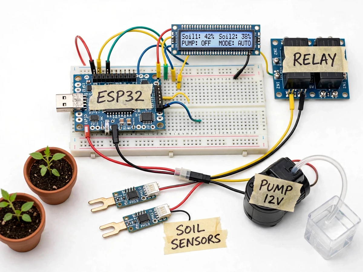
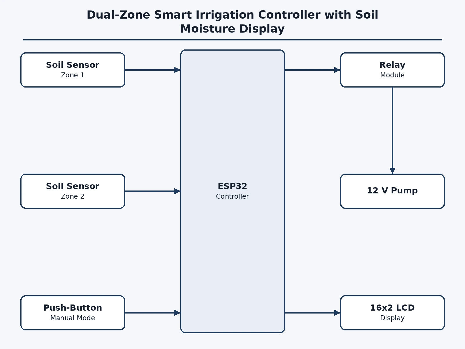
Most DIY irrigation builds are single-zone: one sensor, one pump, everything watered on the same schedule. Real gardens and balcony farms do not work that way — soil composition, sunlight and plant type differ from pot to pot, so a single schedule either drowns one plant or starves another. At the same time, manual watering is wasteful and unreliable when nobody is home. This project builds a dual-zone controller on an ESP32: two capacitive soil-moisture sensors are sampled continuously, each compared against its own configurable threshold, and a relay switches a 12 V pump when either zone calls for water. A 16x2 LCD always shows Soil1 and Soil2 percentages, the pump state and the current mode, so the system's behavior is visible at a glance without any phone or cloud account.
Capacitive probe in zone 1, averaged over 16 samples.
Follow the working sequence
How it works
- Each capacitive soil probe is powered at 3.3 V and its analog output is read by a separate ESP32 ADC channel, averaged over 16 samples to reject noise.
- The firmware converts each raw reading to a moisture percentage using the two-point wet/dry calibration recorded during the buyer's calibration run.
- Every second the loop compares each zone's moisture against its dry threshold (minus a hysteresis band) and decides whether that zone is calling for water.
- If either zone calls, the ESP32 energizes the relay module; the 12 V pump starts and delivers water to both zones until the calling zone reaches its wet threshold.
- The 16x2 LCD refreshes each cycle with Soil1 and Soil2 percentages, PUMP ON/OFF and MODE (AUTO/MAN), so the control decision is always visible.
- A run-time guard stops the pump if it runs longer than the configured maximum (typically ~5 minutes), guarding against a dry tank or detached hose.
- MANUAL mode bypasses the thresholds: the push-button runs the pump directly for priming or demonstration, with the guard timer still active.
Tech stack:
- ESP32 development board
- Capacitive soil-moisture sensor modules (x2)
- 2-channel relay module, opto-isolated
- 12 V DC diaphragm water pump
- 16x2 character LCD
- Arduino IDE (C/C++ firmware)
- JST-XH detachable sensor leads
- 12 V power adapter
| Parameter | Value |
|---|---|
| Moisture channels | 2 independent zones |
| Moisture range | Approximately 0–100% (calibrated) |
| Calibration | Two-point wet/dry, buyer-performed procedure |
| Pump supply | 12 V DC (design target: up to ~2 A stall) |
| Control outputs | 1 relay channel, NO/COM |
| Display | 16x2 character LCD, refreshed ~1 Hz |
| Sampling | 16-sample average per channel, ~1 s loop |
| Max pump run time | Approximately 5 min (configurable) |
| Controller power | 5 V via USB or 12 V via buck converter |
Project features
- [Dual-zone moisture sensing] Two capacitive soil-moisture probes are sampled by the ESP32's ADC and converted to percentage, so zones with different plants get different water thresholds.
- [Relay-driven 12 V pump control] The pump switches through an opto-isolated relay module sized for the pump's stall current, with flyback protection on the coil.
- [Live LCD status display] A 16x2 LCD continuously shows Soil1 and Soil2 moisture, PUMP ON/OFF and the active mode — the full system state is readable without a serial console.
- [Auto and manual modes] AUTO waters each zone against its threshold with configurable hysteresis; MANUAL lets the pump be run from the push-button for priming, flushing or demonstration.
- [Per-zone configurable thresholds] Each zone's dry and wet thresholds are set as constants in firmware with a tuning procedure, documented with the soil types tested.
- [Pump run-time guard] A maximum single-run time stops the pump if a sensor disconnects or a pipe leaks, protecting against flooding and dry-run burnout.
- [Modular zone wiring] Each zone's sensor uses a detachable JST lead, so a probe can be replaced or a zone relocated without re-soldering.
What is included
- Wired dual-zone prototype: ESP32, two soil sensors, relay module, 12 V pump, 16x2 LCD, push-button
- Complete Arduino firmware with auto/manual modes, hysteresis and run-time guard
- Wiring diagram and bill of materials with exact part numbers
- Two-point calibration procedure for moisture percentages
- Project report PDF (background, sensing theory, circuit and firmware design)
- PPT presentation for final review
- Viva Q&A preparation document (ADC sampling, hysteresis, relay protection)
Limitations & prerequisites
- Capacitive probes need recalibration when moved to a very different soil type — the procedure takes about 15 minutes per zone.
- The two zones share one pump, so both zones receive water whenever either calls — the design suits nearby pots, not distant field plots.
- The controller itself is not weatherproof; the electronics enclosure is expected to sit under cover outdoors.
- The pump's lift head is limited to the 12 V diaphragm pump's datasheet rating (approximately 2–3 m) — not a deep-well solution.
- The LCD shows percentages derived from the calibration points; values between them are interpolated, not laboratory moisture figures.
- No cloud dashboard or remote control in the base build — those are listed as future scope.
Frequently Asked Questions
Why two zones instead of one?
Because different plants and soils dry at different rates. One sensor waters everything on a single schedule and typically over-waters one pot while under-watering another; two probes with separate thresholds let each zone be watered by need.
How are the moisture percentages calibrated?
The buyer runs a two-point procedure: read the sensor in air-dry soil and in saturated soil, enter the two values in firmware, and all intermediate readings are mapped linearly between them. The included guide walks through it.
What protects the pump if a hose falls off?
A run-time guard in firmware stops the pump after the configured maximum single run (about 5 minutes), and the pump also stops immediately in MANUAL mode when the button is released. It does not protect against a continuously pressurized mains line.
Can I add a third zone?
Yes — the ESP32 has spare ADC channels, and the firmware's zone table is designed to accept one more sensor; the report's future-scope section documents exactly what changes.
Does the system need Wi-Fi or an app?
No. The base build is fully local: sensing, control and display all run on the ESP32 with no network dependency, which is deliberate for garden reliability. A Wi-Fi dashboard is future scope.
Is this project suitable for a final-year project?
Yes — for Electronics, Electrical and IoT programs. It combines analog sensing, calibration, relay power control, state-machine firmware and a live display in one demonstrable build. Suitable for B.E./B.Tech final-year projects in Electronics, Electrical and IoT.
Components & software requirements
- ESP32 development board
- Capacitive soil-moisture sensor modules (x2)
- 2-channel relay module, opto-isolated
- 12 V DC diaphragm water pump
- 16x2 character LCD
- Arduino IDE (C/C++ firmware)
- JST-XH detachable sensor leads
- 12 V power adapter
Delivery information
Built-to-order project. Delivery timeline is shared after order confirmation based on current queue.
Support terms
Complete documentation, setup guide, and viva preparation included. Support for setup and explanation provided.
Download free synopsis (PDF)
Enter your name and WhatsApp number — the synopsis PDF downloads immediately. We may send occasional project updates on WhatsApp; no spam.