
More project photos (2)
The problem
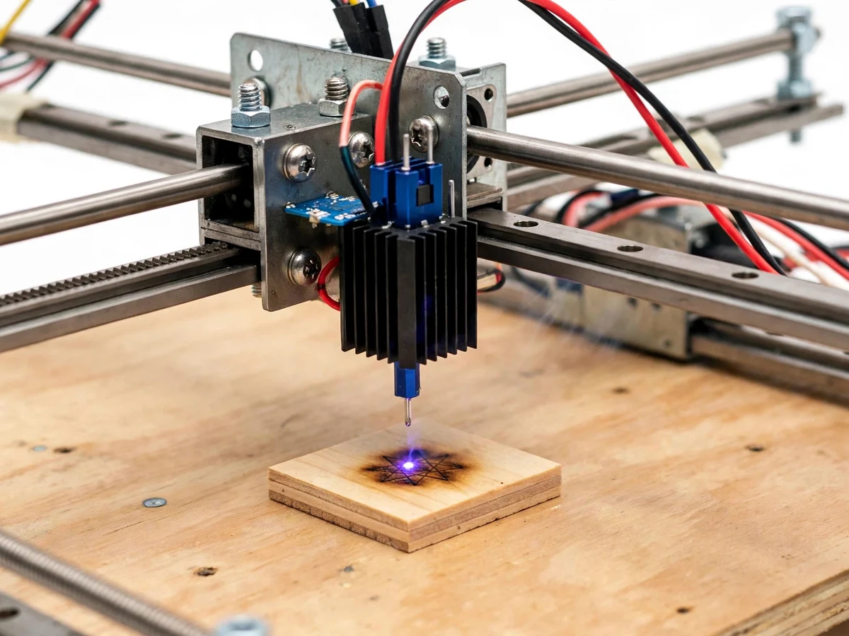
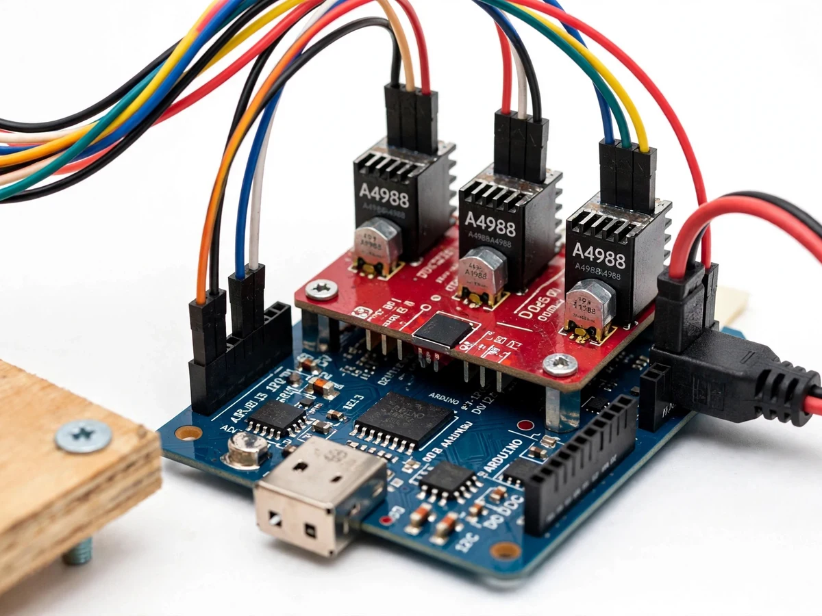
A DIY laser engraver using Arduino and DVD-drive stepper motors is a two-axis CNC machine that burns text and images into wood, paper and leather with a blue laser beam. Commercial engravers cost tens of thousands of rupees and hide their motion control inside proprietary boards, so the student learns nothing about how it moves; this build answers that with parts a student can afford — two stepper sleds salvaged from discarded DVD drives, an Arduino Uno carrying a CNC shield and A4988 stepper drivers, and a 445 nm laser diode module. On the PC, LaserGRBL turns an image into G-code; on the Arduino, GRBL 1.1h firmware converts that G-code into step pulses driving the two sleds across a roughly 40 × 40 mm work area (design target). Because every axis moves on a real lead screw and the laser fires under software PWM control, the build teaches steps-per-mm calibration, motion planning and laser-safety discipline.
The gap this engraver closes is practical: CNC motion control is usually taught as equations — pulse counts, lead-screw pitch, duty cycle — while the only affordable machines students can touch hide all of it inside closed firmware. Here every one of those equations is visible and touchable: change GRBL's $100 setting and the machine visibly stretches or compresses the same drawing. Builder note from a real build: a salvaged sled's dried-up grease is the single most common cause of stuttering axes — clean the rails and re-grease the lead screw before assembly, and check the two axes are square with an engraved test square, because a skewed frame turns every engraved square into a parallelogram.
Free PC software that rasterizes the artwork into G-code and streams it.
Follow the working sequence
How it works
The full journey from an idea to a burnt line runs design → G-code → GRBL → steppers and laser → engraved piece. It starts on the PC, where an image or text is prepared in LaserGRBL and converted into G-code — a list of move-to and laser-on/off commands. That G-code streams over USB into the Arduino Uno, where GRBL 1.1h firmware plans each move under acceleration limits and converts it into precisely timed step pulses for the two A4988 drivers' STEP and DIR pins. The drivers rotate the DVD sled steppers in 1/16 microsteps; each lead-screw turn converts rotation into linear travel, moving the laser head across the work area. The Arduino's PWM output drives the diode's TTL input — in laser mode ($32=1) the beam fires only while the head is moving, so corners do not burn darker. The focused spot traces the path and burns the design into the material.
- Prepare the artwork on the PC: a black-and-white image or text, sized to the approximately 40 × 40 mm work area (design target).
- LaserGRBL rasterizes the artwork into G-code, mapping dark pixels to laser-on moves with the chosen power and speed.
- The G-code streams over USB serial (115200 baud, typical) to the Arduino running GRBL 1.1h.
- GRBL plans each move under its acceleration limits and emits timed step pulses to the two A4988 drivers; the drivers microstep the DVD sled motors (1/16) and the lead screws convert rotation into X/Y travel.
- The Arduino's PWM pin drives the laser module's TTL input; with laser mode $32=1 the beam fires only during cutting moves, and the duty cycle sets burn darkness.
- After the first run, steps/mm ($100, $101) are calibrated against a ruler-engraved test pattern and focus is set to the smallest burn dot; the machine is then ready for repeatable engravings.
Tech stack:
- Arduino Uno · GRBL 1.1h firmware
- CNC shield V3 · A4988 stepper drivers
- Salvaged DVD-drive stepper sleds (X/Y)
- 445 nm laser diode module · 500 mW class
- LaserGRBL G-code sender (PC)
- 12 V DC power supply
- Plywood frame · lead-screw axes
- PWM laser power control
| Parameter | Value |
|---|---|
| Controller | Arduino Uno (ATmega328P, datasheet value) |
| Firmware | GRBL 1.1h (open-source CNC firmware) |
| Stepper drivers | A4988 × 2, 1/16 microstepping (CNC shield V3 jumpers) |
| Sled stepper | 18° step angle · 20 steps/rev (typical for salvaged DVD sleds) |
| Lead screw | Approximately 3 mm lead (typical salvaged sled) |
| Steps per mm | Approximately 106.7 (calculated: 320 microsteps ÷ 3 mm; calibrated per build) |
| Laser module | 445 nm blue diode, 500 mW class (design target) |
| Work area | Approximately 40 × 40 mm (design target) |
| Laser control | TTL/PWM input, GRBL laser mode ($32 = 1) |
| PC software | LaserGRBL, USB serial at 115200 baud (typical) |
| Power | 12 V DC adapter for shield and laser driver (typical) |
Project features
The four capabilities that carry this engraver are its GRBL-powered motion control, the salvaged DVD-drive axes, PWM laser power control, and the LaserGRBL image-to-G-code workflow. GRBL 1.1h on the Arduino Uno is the same open-source motion firmware used by hobby CNC machines: it accepts standard G-code over USB, plans each move under acceleration limits, and converts it into precisely timed step pulses on the A4988 drivers' STEP and DIR pins. The X and Y axes are stepper sleds pulled from discarded DVD drives — 18° step-angle motors driving roughly 3 mm lead screws — which is what keeps the whole build at a student budget while still resolving fine engraving detail. The 445 nm blue diode fires under software PWM, so the same design engraves light on pale wood and dark on leather just by changing power and speed. LaserGRBL on the PC closes the loop: drop in any black-and-white image and it produces the G-code the machine burns.
- [GRBL 1.1h motion control] The Arduino runs the same open-source CNC firmware used in hobby routers: it accepts standard G-code over USB serial and plans every move with acceleration limits so the small sled motors never stall.
- [Salvaged DVD-drive X/Y axes] Two stepper sleds from discarded DVD drives form the gantry — 18° step-angle motors on roughly 3 mm lead screws — keeping the build genuinely student-budget without sacrificing fine detail.
- [PWM laser power control] The 445 nm diode module (500 mW class, design target) fires through a TTL/PWM input, so engraving depth and darkness are set in software per material.
- [LaserGRBL workflow] The free PC software converts images and text into G-code, previews the burn, and streams it to the Arduino — no paid software anywhere in the chain.
- [Steps-per-mm calibration] GRBL's $100/$101 settings are computed from the sled's own lead screw (320 microsteps ÷ ~3 mm ≈ 106.7 steps/mm, design target) and fine-tuned with a ruler-engraved test pattern.
- [Laser-safety hardware] An arm/disarm switch with an indicator LED keeps the diode off during setup, GRBL's laser mode ($32=1) fires the beam only during cutting moves, and OD-rated 445 nm goggles ship with the build.
- [Material presets] Starting power-and-speed profiles for plywood, paper and leather are documented, so the first engraving does not begin with blind trial and error.
Optional customizations (not in the base build, available on request): a larger work area using longer rails and bigger steppers, or a rotary attachment for engraving cylinders. Future scope (not included): a camera overlay for aligning designs on the workpiece, and a fume-extraction enclosure.
What is included
- Fully assembled engraver: plywood frame, two salvaged DVD-drive axes, laser module, Arduino Uno + CNC shield with A4988 drivers
- Arduino flashed with GRBL 1.1h, axis steps/mm ($100/$101) calibrated for the build
- Wiring diagram, component list and the salvaged-part preparation notes (cleaning, re-greasing, squaring the axes)
- LaserGRBL setup guide with power/speed starting presets for plywood, paper and leather
- Laser-safety checklist and OD-rated 445 nm safety goggles
- Project report PDF, PPT presentation and viva Q&A document
- Estimated build timeline: 2–3 weeks from order confirmation (estimate, not a delivery commitment)
- Setup support: the wiring and LaserGRBL guides include troubleshooting steps for common first-run issues
Limitations & prerequisites
- The 500 mW-class 445 nm diode is a serious eye hazard: OD-rated goggles are mandatory whenever the machine is powered, and the beam or its reflection must never be viewed directly.
- Never engrave PVC, vinyl or any chlorinated plastic — the laser releases toxic hydrogen-chloride fumes from these materials.
- Engrave only in a ventilated space; even wood and paper produce smoke that must be extracted or vented outdoors.
- A low-power diode engraves wood, paper, card and leather — it cannot engrave or cut metal, glass or stone, and cutting through thick wood is out of scope.
- The work area is approximately 40 × 40 mm (design target) — a small desktop machine, not a production engraver.
- Salvaged sleds differ between drives, so steps/mm and focus must be calibrated per build; exact settings cannot be copied from another machine.
- The base build has no safety enclosure or interlock lid; it is an academic prototype, not a certified industrial machine.
Frequently Asked Questions
How does the machine move the laser so precisely?
GRBL firmware on the Arduino converts each G-code move into precisely timed step pulses sent to the two A4988 stepper drivers. The drivers rotate the salvaged DVD sled motors in 1/16 microsteps, and each lead screw turns that rotation into linear travel — about 106.7 steps per millimetre (calculated from 320 microsteps per revolution over an approximately 3 mm lead). The motion runs open-loop with no encoders, so repeatability depends on the calibration: the build procedure engraves a test pattern against a ruler, and the report documents how steps/mm drift if a sled is re-greased or re-seated.
Why DVD-drive motors instead of standard NEMA 17 steppers?
Cost and resolution. A salvaged DVD sled carries its own precision lead screw and a smooth 18° step-angle motor — the pair delivers roughly 0.01 mm of theoretical resolution per microstep at a fraction of the cost of a NEMA 17 plus a separate lead screw and couplers. Two discarded drives supply both axes, which is what keeps this a genuinely student-budget build. The trade-off is small torque and a small work area; a NEMA-based build would be faster and larger but costs several times more, and is quoted as an optional customization.
What can it engrave, and what must it never touch?
It engraves wood (plywood, MDF offcuts), paper, card and leather well, and can mark anodized aluminium coatings. It must NEVER engrave PVC, vinyl or any chlorinated plastic — the beam releases toxic hydrogen-chloride fumes — and it cannot engrave or cut metal, glass or stone at the 500 mW class (design target). Starting power-and-speed presets for the safe materials are documented in the build guide, and every engraving session needs ventilation because even wood produces smoke.
Is the laser safe to use?
No laser is safe without discipline, and this build treats safety as part of the project, not an afterthought. OD-rated 445 nm goggles are mandatory whenever the machine is powered, the diode stays off during setup behind an arm switch with an indicator LED, and GRBL's laser mode fires the beam only while the head is moving. The machine must be supervised for its entire run and operated in a ventilated space; the build ships with a written safety checklist, not just a warning sticker.
Can the work area be made bigger?
Yes, as an optional customization — longer rails and larger steppers replace the DVD sleds, with GRBL's steps/mm recalibrated for the new mechanics. The base build keeps the approximately 40 × 40 mm salvaged-sled work area (design target) because that is what the student budget allows. A larger build needs a stiffer frame and a higher-power laser driver, so it is scoped and quoted separately rather than promised as a drop-in change.
Is this project suitable for a final-year project?
Yes — for Electronics and Telecommunication programs. It demonstrates embedded firmware (GRBL on Arduino), stepper-motor driving with the A4988, CNC motion planning, PWM power control and laser safety — a complete electromechanical system with visible cause and effect between code and motion. The build, the per-machine calibration and the safety discipline all make strong viva material, and the scope fits one semester.
Components & software requirements
- Arduino Uno · GRBL 1.1h firmware
- CNC shield V3 · A4988 stepper drivers
- Salvaged DVD-drive stepper sleds (X/Y)
- 445 nm laser diode module · 500 mW class
- LaserGRBL G-code sender (PC)
- 12 V DC power supply
- Plywood frame · lead-screw axes
- PWM laser power control
Delivery information
Built-to-order project. Delivery timeline is shared after order confirmation based on current queue.
Support terms
Complete documentation, setup guide, and viva preparation included. Support for setup and explanation provided.
Download free synopsis (PDF)
Enter your name and WhatsApp number — the synopsis PDF downloads immediately. We may send occasional project updates on WhatsApp; no spam.