
More project photos (2)
The problem
The classic clap switch is a one-trick circuit: clap once, the light toggles. This project takes the idea seriously and builds a multi-level controller out of it — counting claps instead of merely detecting them turns one binary input into four commands, enough to run a fan's speed steps hands-free. The engineering is in two places: the acoustic front end, which must catch a clap's sharp transient while ignoring conversation and TV audio, and the power stage, where a triac with zero-cross timing regulates a real AC fan. Together they make a touchless controller that is genuinely usable and a strong demonstration of signal conditioning plus power electronics.
How it works
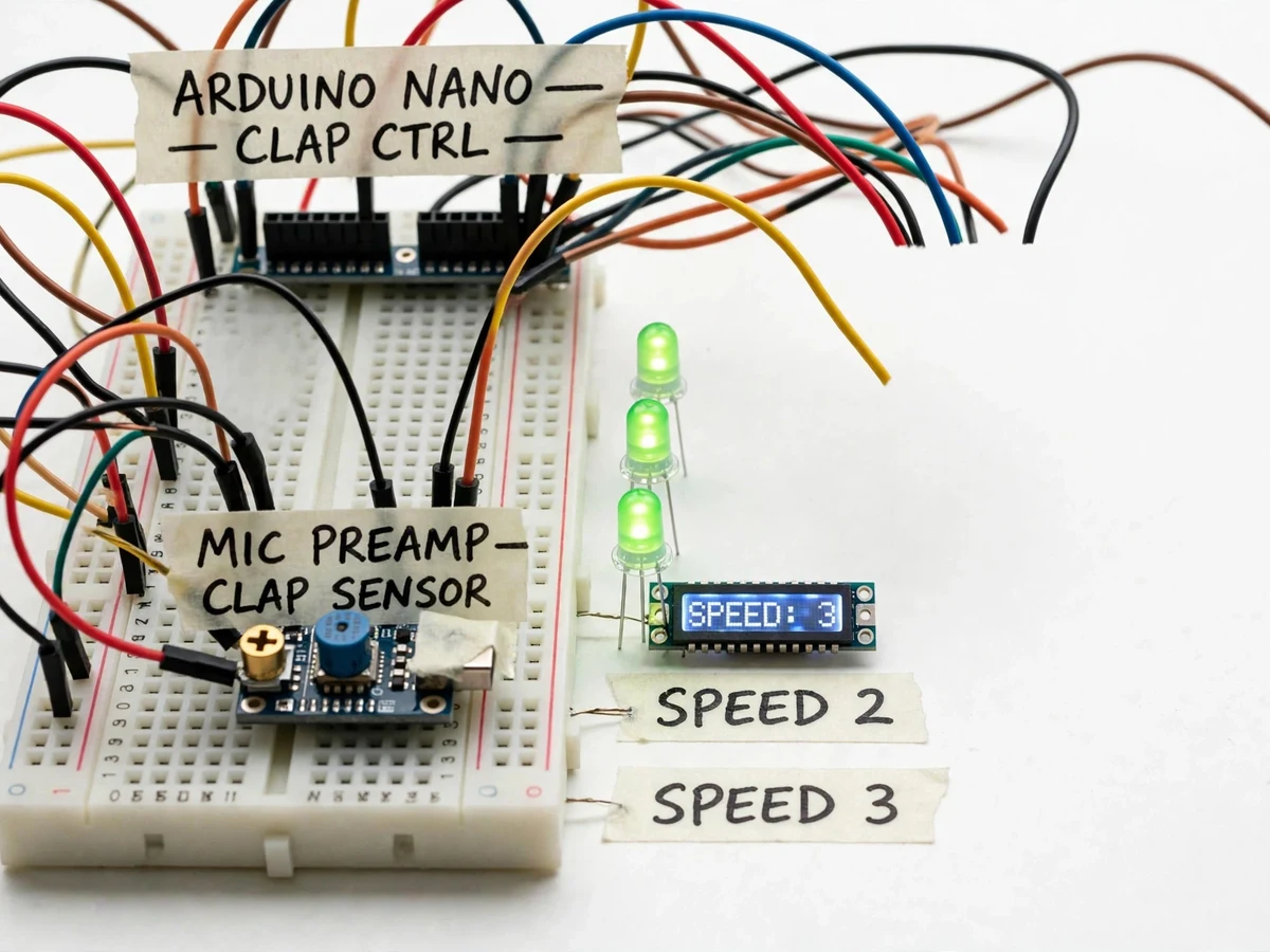
- The electret microphone picks up room sound; the preamplifier boosts it and the comparator fires a digital pulse on sharp transients.
- Firmware timestamps each pulse and counts how many arrive inside the 1.5-second clap window, ignoring pulses closer together than the debounce gap.
- One clap sets speed 1, two claps speed 2, three claps speed 3, four claps switch the fan off.
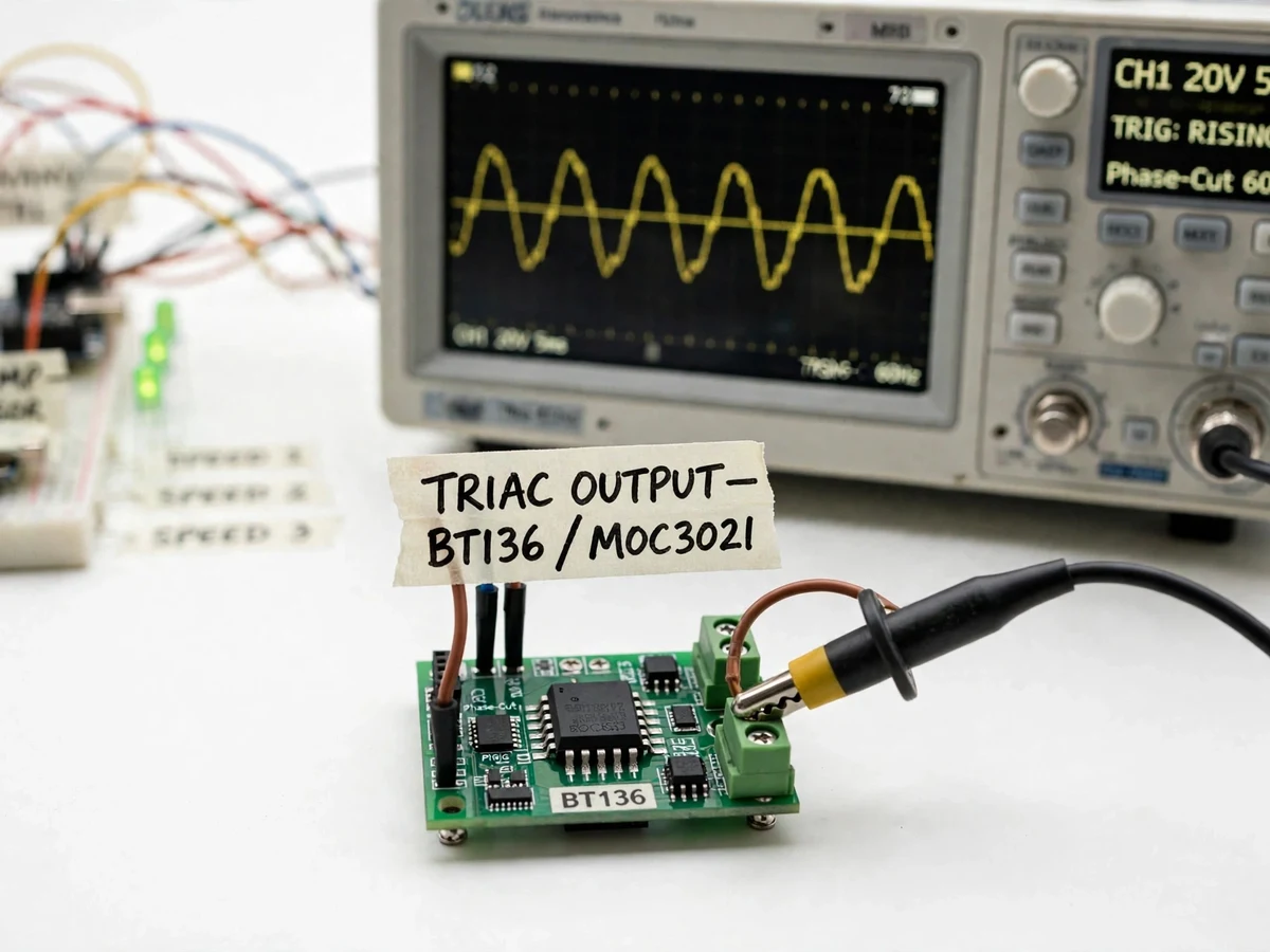
- The selected speed maps to a triac firing angle; the zero-cross detector keeps every firing synchronized to the mains cycle.
- The triac conducts for the chosen fraction of each half-cycle, regulating the fan motor's effective voltage.
- The speed LEDs update on every valid command, and the manual override switch forces full speed regardless of clap state.
Tech stack:
- Arduino Nano (ATmega328P)
- Electret microphone + preamplifier/comparator
- BT136 triac · MOC3021 optocoupler
- Zero-crossing detector circuit
- 3-LED speed indicator
- 230V AC fan demo load
- Potentiometer sensitivity trim
| Parameter | Value |
|---|---|
| Command set | 1 clap = low, 2 = medium, 3 = high, 4 = off |
| Clap window | 1.5 s counting window (firmware, design) |
| Speed steps | 3 triac firing angles + off |
| Detection range | Claps within approximately 3–4 m in a quiet room (expected) |
| Supply | 230V AC, 50 Hz fan load (design) |
| Load rating | Up to 80W fan motor (design target) |
| Sensitivity | Potentiometer-adjustable comparator threshold |
| Build type | Breadboard/PCB prototype with table-fan demo load |
Project features
- [Clap counting, not just detection] Firmware counts 1–4 claps inside a 1.5-second window to select low, medium, high or off — four commands from one microphone.
- [Electret-mic front end] Microphone with preamplifier and comparator converts the clap transient into a clean digital pulse.
- [False-trigger filtering] Amplitude threshold plus minimum-gap timing rejects speech, TV audio and single knocks; the sensitivity is potentiometer-adjustable.
- [Triac fan regulation] Zero-cross synchronized triac phase-cut drives the fan at three real speed steps.
- [Speed indicator LEDs] Three LEDs show the active speed level at a glance.
- [Manual override switch] A physical switch bypasses clap control for users who just want the fan on.
- [Startup calibration] Power-on self-check confirms the mic chain and triac stage before accepting claps.
What is included
- Working clap-counting fan controller prototype with demo fan
- Arduino firmware (clap counting, debounce, triac timing, LED indication)
- Full wiring diagram and mic/triac placement documentation
- Sensitivity-tuning and false-trigger test procedure
- Project report PDF (acoustic detection, clap transient analysis, triac fan control, measurements)
- PPT presentation for final review
- Viva Q&A preparation document (electret biasing, comparator thresholding, zero-crossing, motor speed control)
Limitations & prerequisites
- Loud continuous noise (music, TV at high volume) can mask claps or cause false counts — this is a teaching controller, not a noise-immune industrial input.
- Triac phase-cut fan control can produce an audible motor hum at low speeds on some fans; the report documents this as a known characteristic.
- Detection range of 3–4 m is an expected figure in a quiet room; reflective rooms and background noise reduce it, and the student verifies their own range.
- The 1.5-second window means commands take a beat to register — it is deliberate counting, not instant reaction.
- Only the four defined clap patterns are recognized; there is no voice or pattern learning in the base build.
Frequently Asked Questions
How is this different from a simple clap switch?
A clap switch toggles on one clap. This controller counts — it measures how many claps arrived inside a 1.5-second window and maps the count to four different fan states. Counting needs timestamping and debounce logic; detection alone does not.
Won't talking or the TV trigger it?
The comparator threshold is set above normal speech levels, and the firmware requires the sharp attack transient of a clap plus a minimum gap between pulses. The included procedure tunes the threshold for the student's own room.
Why does the fan hum at low speed?
Triac phase-cut chops the sine wave, and the motor's windings vibrate at the resulting harmonic content. It is a documented trait of triac fan regulators, not a fault.
How does the triac set three speeds?
Each speed is a different firing angle after the zero-crossing. Earlier firing delivers more of each half-cycle to the motor (faster); later firing delivers less (slower).
What if I clap five times by accident?
Counts above four are ignored and the window resets — the fan keeps its current state rather than doing something unexpected.
Is this project suitable for a final-year project?
Yes — for Electronics programs. It combines analog signal conditioning, embedded timing logic and mains power control in one demonstrable build. Suitable for B.E./B.Tech final-year projects in Electronics.
Components & software requirements
- Arduino Nano (ATmega328P)
- Electret microphone + preamplifier/comparator
- BT136 triac · MOC3021 optocoupler
- Zero-crossing detector circuit
- 3-LED speed indicator
- 230V AC fan demo load
- Potentiometer sensitivity trim
Delivery information
Built-to-order project. Delivery timeline is shared after order confirmation based on current queue.
Support terms
Complete documentation, setup guide, and viva preparation included. Support for setup and explanation provided.