
More project photos (2)
The problem
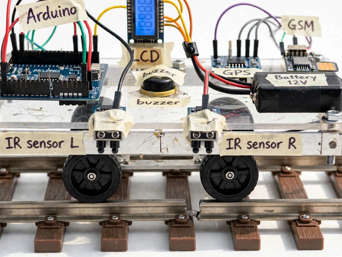
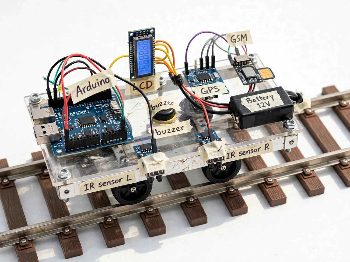
The Automatic Railway Track Crack Detection with IR Sensors and GPS Alert is a rail-running inspection frame that travels along a track and watches the rail head for cracks and gaps. The Automatic Railway Track Crack Detection system carries IR sensors aimed at the rail head, an Arduino controller that reads those sensors, and a GPS receiver paired with a GSM module that sends an alert with the location whenever a crack or gap is detected. Manual track inspection relies on patrol teams walking sections of track and checking the rail by eye, which is slow and easy to get wrong when a hairline crack hides under rust or dust. A missed crack can grow under repeated train loads until the rail breaks, while a false alarm sends a crew to the wrong place. This project demonstrates a repeatable alternative: a low-cost frame that scans the same way on every run and reports a location a crew can go to.
This is a built-to-order hardware project: the inspection frame, firmware, wiring diagram, component list, calibration procedure and test pieces are prepared for the order, and the frame is tested on a bench rail section before handover.
Builder note from the build: calibrating the IR threshold on a rusted rail section behaved differently from calibrating on a clean rail section. On the rusted section the reflected reading sat noticeably lower than on the clean polished section, so a threshold copied from the clean rail alone flagged rust as a crack, and a threshold set from the rusted rail alone missed the sample gap. The working threshold was therefore set between the two readings, after measuring both surfaces in the same light, and then rechecked after dust was brushed onto the rail. That two-surface calibration step is part of the handover procedure, because a single-surface threshold is the most common reason this kind of build misbehaves outside the lab.
Two IR modules aimed at the rail head read reflected infrared light as the frame travels.
Follow the working sequence
How it works
The Automatic Railway Track Crack Detection with IR Sensors and GPS Alert works end to end as one continuous loop from rail surface to phone alert. The frame is placed on a test rail section with its wheels seated on the rail head, powered on, and started by the operator, and it then drives itself along the rail while its IR sensors watch the rail head and its Arduino controller compares every reading against a calibrated threshold. When a crack or gap breaks the reflected infrared pattern and a reading crosses the threshold, the controller treats it as a detection: it stops the drive motors there, sounds the buzzer, and shows CRACK DETECTED on the LCD. The GPS module then supplies the coordinates of the stopped position, the controller formats them into a text message, and the GSM module sends it to the configured number, after which the LCD shows ALERT SENT and the frame waits for inspection and restart.
- The frame is placed on a test rail section with its wheels seated on the rail head, powered from its battery pack, and the LCD shows READY once the controller, GPS module and GSM module have started.
- The operator presses start, and the DC gear motors drive the frame slowly and steadily along the rail while the IR sensor modules watch the rail head continuously.
- Each IR sensor emits infrared light onto the rail head and reads the reflected signal, producing a reading that stays steady over intact rail and changes sharply over a crack or gap.
- The Arduino reads both IR sensors in turn and compares every reading with the calibrated threshold value stored in the firmware, rejecting ordinary surface variation that stays on the normal side of the threshold.
- When a reading crosses the threshold, the controller flags a detection, stops the drive motors at that point, sounds the buzzer, and changes the LCD display to CRACK DETECTED.
- The Neo-6M GPS module supplies the latitude and longitude of the stopped position, and the controller formats those coordinates into a short crack-detected text message.
- The SIM800L GSM module sends that SMS to the configured mobile number, the LCD changes to ALERT SENT, and the frame waits for the operator to inspect the flagged point, reset the detection, and restart the run.
Tech stack:
- Arduino Uno (ATmega328P)
- IR sensor modules · rail-head scanning
- Neo-6M GPS module
- SIM800L GSM module
- DC gear motors · rail wheels
- 16x2 LCD · buzzer
- 12 V DC battery pack
- Arduino IDE · Embedded C
| Parameter | Value |
|---|---|
| Controller | Arduino Uno with ATmega328P microcontroller (datasheet component) |
| IR sensors | 2 units (sensor pair mounted over one rail head) |
| GPS module | Neo-6M GPS receiver (datasheet component) |
| GPS accuracy | Approximately 2.5 m CEP (datasheet value, open-sky conditions) |
| GSM module | SIM800L GSM module (datasheet component, needs a valid SIM and mobile coverage) |
| Display | 16x2 character LCD (display component) |
| Local alert | Buzzer, sounded at detection (local alert component) |
| Drive | DC gear motors with rail-seated wheels (drive component) |
| Power supply | 12 V DC battery pack (nominal supply value) |
| Battery runtime | Approximately 1–2 hours per charge (expected, load-dependent) |
| Detection indication | Gap or crack wider than approximately 3 mm (design target, checked with a sample gap piece during handover) |
| Operating setting | Test rail section only (demonstration setting, never an operational railway line) |
Project features
The Automatic Railway Track Crack Detection with IR Sensors and GPS Alert gives a student a complete, demonstrable inspection loop rather than a sensor on a bench. The top capabilities are IR rail-head scanning, threshold-based crack flagging, GPS location tagging with a GSM SMS alert, and local buzzer plus LCD status, all carried on one battery-powered frame that runs along a test rail. IR scanning watches the rail head continuously as the frame moves, threshold flagging turns a raw reflection reading into a yes-or-no detection decision, GPS tagging fixes where that decision happened, and the GSM alert carries that location to a phone so the detection is useful beyond the bench. The buzzer and LCD make the moment of detection visible and audible to anyone watching, without needing to read a serial monitor. Together these capabilities let a student explain sensing, decision logic, motor control, satellite positioning and mobile messaging in a single working prototype.
- [IR rail-head scanning] Two IR sensor modules mounted low over the rail head emit infrared light and read the reflection from the rail surface as the frame travels. A continuous, steady reflection means intact rail; a crack or gap breaks that reflection pattern, which is the raw signal every later step works from.
- [Threshold-based crack flagging] The Arduino compares each IR reading with a calibrated threshold value stored in the firmware. Only a reading that crosses the threshold is treated as a detection, so ordinary surface variation does not trigger an alert, and the threshold itself is set with the two-surface calibration procedure described above.
- [GPS location tagging] A Neo-6M GPS module supplies latitude and longitude at the moment of detection, after the frame has stopped at the flagged point. The coordinates describe where the frame stopped, not an estimated position along the run, so the reported location matches the point an inspector would walk to.
- [GSM SMS alert] A SIM800L GSM module sends an SMS to a configured mobile number carrying a crack-detected message with the GPS coordinates from the moment of detection. The alert is a plain text message, so it can be received on any phone without an app, a data plan, or a cloud account.
- [Buzzer and LCD status] A buzzer sounds at the moment of detection and a 16x2 LCD shows the frame state in plain words: READY while running, CRACK DETECTED at the flagged point, and ALERT SENT once the SMS has gone out. The local signals work even where there is no mobile coverage, so a detection is never silent.
- [Rail-running drive] DC gear motors drive wheels shaped to sit on the rail head, so the frame follows the track instead of needing steering. Travel is deliberately slow and steady, set by the motor gearing and the supply voltage, because a fast frame would pass a narrow gap between sensor samples.
- [Manual start, stop and reset] A start switch begins a run, the frame stops itself on detection, and a reset control clears the flagged state so the operator can inspect the point, note it, and restart the run. The operator stays in control of every run, and no run continues past a flagged point unexamined.
Implemented in the base build: all features above. Optional customization on request: a second IR sensor pair for the other rail, SD-card logging of detection coordinates, or a solar charging add-on for the battery pack. Future scope, not included: camera verification of flagged points or a cloud dashboard of past detections.
What is included
- Assembled rail-running inspection frame with Arduino, IR sensors, GPS and GSM modules
- Firmware source code with the calibrated threshold procedure
- Wiring diagram with labelled sensor, motor, GPS and GSM connections
- Component list with controller, sensor and module details
- Two-surface IR calibration procedure (clean rail section and rusted rail section)
- Sample gap test piece for demonstrating a detection during handover
- Project report material covering working, calibration and limitations
- Project abstract PDF
- Demonstration guidance for running, flagging, alerting and resetting the frame
Timeline
- Indicative timeline: approximately 2–3 weeks from order confirmation for assembly, wiring, calibration and bench-rail testing, subject to component availability. The calibration step is done last, after the frame runs cleanly, because the threshold is only meaningful once the sensors sit at their final height over the rail.
Support
- Support: demonstration guidance plus fault-finding help for the calibration, GPS fix and GSM alert steps during the handover demonstration, and an explanation of the firmware threshold logic so the student can describe each step from sensor reading to SMS alert.
Limitations & prerequisites
- IR sensing is affected by heavy rust, mud, standing water and strong direct sunlight, so the threshold must be recalibrated when the rail surface or lighting changes substantially; a single threshold does not suit every surface.
- The base build scans one rail head per run: inspecting the other rail needs a second run with the frame moved across, and a second sensor pair is an optional customization, not part of the base build.
- GPS coordinates are only as good as the satellite fix at the flagged point: the Neo-6M datasheet value is approximately 2.5 m CEP in open-sky conditions, and fixes are slower or less accurate indoors, under cover, or beside tall structures.
- The GSM alert needs mobile network coverage and a valid SIM with balance; where there is no coverage the buzzer and LCD still report the detection locally, but no SMS is sent until coverage returns.
- Battery runtime is approximately 1–2 hours per charge (expected, load-dependent), so long demonstration sessions need a recharge break, and runtime falls as motor load and stop-start cycles increase.
- This is an academic demonstration prototype for a test rail section only: it is not a certified railway inspection system, it must never be placed on an operational railway line, and no detection claim is made for cracks hidden under ballast, paint, or heavy corrosion.
Frequently Asked Questions
Is this project suitable for a final-year project?
Yes, for B.E./B.Tech Electronics and Telecommunication programmes, because the build combines sensor interfacing, threshold-based signal decision-making, motor control, GPS parsing, and GSM communication in one working prototype that can be demonstrated on a test rail section, with each stage visible from sensor reading to SMS alert. The demonstration runs from sensor reading to SMS alert in front of reviewers, and each stage maps to a concept that can be explained from the wiring diagram and firmware.
Which controller and sensors are used?
The build uses an Arduino Uno with an ATmega328P microcontroller and two IR sensor modules mounted low over the rail head, together with a Neo-6M GPS module, a SIM800L GSM module, a 16x2 LCD, a buzzer, and DC gear motors. The Arduino reads the IR sensors continuously, compares each reading with the calibrated threshold, drives the motors, and coordinates the GPS and GSM steps on detection.
How does the IR sensor actually detect a crack?
A crack is detected when it breaks the reflected infrared pattern from the rail head, because each IR sensor emits infrared light onto the rail and reads the reflection, which stays steady over intact rail and changes sharply where a crack or gap interrupts the surface. The Arduino compares that reading with a calibrated threshold, and only a reading crossing the threshold is treated as a detection, which is why the two-surface calibration matters.
What exactly does the SMS alert contain?
The SMS alert contains a short crack-detected message together with the latitude and longitude captured by the GPS module at the stopped position, sent by the SIM800L GSM module to one configured mobile number, so the recipient knows both that a crack was found and exactly where the frame stopped. It is a plain text message readable on any phone without an app or data plan, and the LCD changes to ALERT SENT once the message has gone out.
Does the system work without mobile network or GPS coverage?
Local detection still works without mobile coverage, because the buzzer sounds and the LCD shows CRACK DETECTED at the flagged point even when no SMS can be sent, but the SMS alert itself needs mobile network coverage and a valid SIM. GPS coordinates likewise need an open-sky satellite fix, so the frame should be demonstrated outdoors or in a clear area for the full alert loop.
Can the system inspect both rails or be customized?
The base build inspects one rail head per run, so the other rail needs a second run with the frame moved across, while a second IR sensor pair, SD-card logging of detection coordinates, or a solar charging add-on can be developed as optional customization on request. Camera verification of flagged points and a cloud dashboard of past detections are future scope and are not part of the base build.
Components & software requirements
- Arduino Uno (ATmega328P)
- IR sensor modules · rail-head scanning
- Neo-6M GPS module
- SIM800L GSM module
- DC gear motors · rail wheels
- 16x2 LCD · buzzer
- 12 V DC battery pack
- Arduino IDE · Embedded C
Delivery information
Built-to-order project. Delivery timeline is shared after order confirmation based on current queue.
Support terms
Complete documentation, setup guide, and viva preparation included. Support for setup and explanation provided.
Download free synopsis (PDF)
Enter your name and WhatsApp number — the synopsis PDF downloads immediately. We may send occasional project updates on WhatsApp; no spam.