
More project photos (2)
The problem
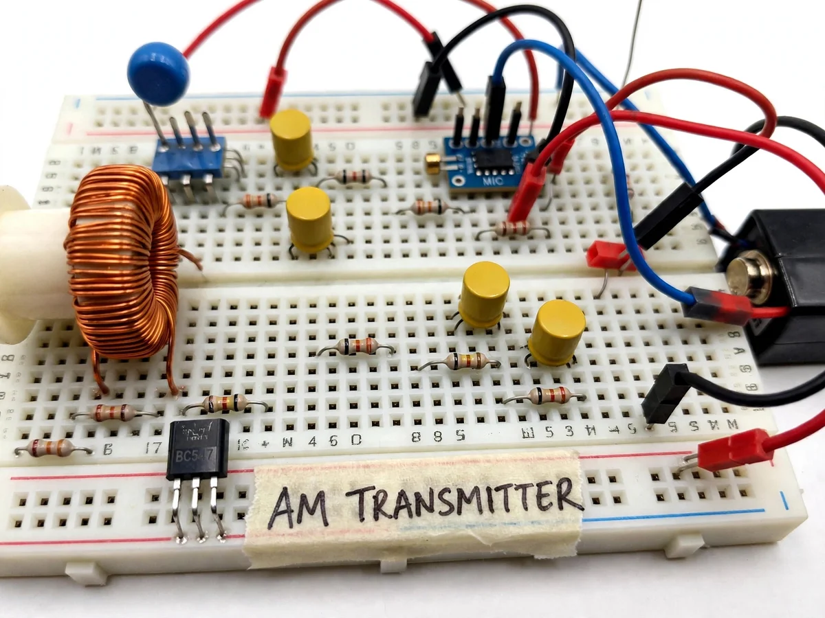
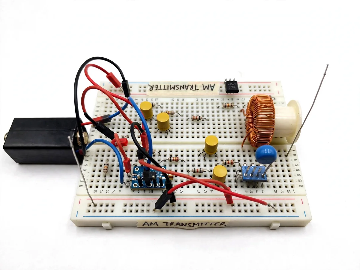
Amplitude modulation is the oldest broadcast technique still on the air, and it remains the clearest way to teach what modulation actually means: a high-frequency carrier whose amplitude is shaped, moment by moment, by the audio signal. This project builds a complete AM transmitter from discrete parts. A BC547 transistor wired as an LC oscillator sustains a carrier in the medium-wave band (design target around 1 MHz, set by a hand-wound coil and tuning capacitor); an electret microphone feeding a simple preamp captures voice; the audio is applied to modulate the transistor's operating point so the carrier amplitude follows the sound; and a whip antenna radiates the result. The demonstration needs no special receiver — any household MW radio tuned to the carrier frequency demodulates it. The student learns the modulation process end to end: carrier generation, resonance, modulation depth, and why the received audio distorts when the modulation is pushed too far. It is deliberately a low-power, room-scale lab demonstration, not a broadcast station.
How it works
- The student winds the tank coil to the specified turns, connects it with the tuning capacitor, and verifies the oscillator starts — a carrier the radio can find.
- The MW radio is tuned across the band until the quiet carrier is located (heard as a silent spot or whistle), marking the transmit frequency.
- The electret microphone stage is powered and its audio output confirmed; speaking into the mic produces the modulating signal.
- The audio is coupled to the oscillator transistor's bias network; voice peaks drive the operating point up and down, so the carrier amplitude follows the audio envelope — amplitude modulation.
- The whip antenna is attached and the student walks the radio a few meters away, hearing their own voice reproduced by the radio's detector.
- The modulation preset is adjusted while listening: too low and the audio is faint, too high and it distorts — demonstrating modulation depth and over-modulation.
- Touching the tank area shows hand-capacitance frequency pulling, and the student re-tunes the radio — a memorable lesson in oscillator stability.
Tech stack:
- AM modulation theory
- LC oscillator design
- Transistor biasing (BC547)
- Electret microphone interfacing
- Tank circuit resonance
- Antenna basics
- Receiver demodulation
- RF prototyping practices
| Parameter | Value |
|---|---|
| Carrier frequency | Medium-wave band, approximately 1 MHz (design target) |
| Oscillator transistor | BC547 (datasheet) |
| Tank circuit | Hand-wound coil, approximately 100 µH, with tuning capacitor (design) |
| Audio input | Electret microphone capsule with preamp (design) |
| Modulation | Amplitude modulation via bias variation; depth set by preset (design) |
| Antenna | Short whip, room-scale radiation (design) |
| Range | A few meters indoors (design target) |
| Supply | 9 V battery (design) |
Project features
- [BC547 LC oscillator] A single-transistor oscillator with a hand-wound tank coil generates the medium-wave carrier — the classic discrete RF stage.
- [Hand-wound tank circuit] The coil is wound by hand on a former with a tuning capacitor, so resonance is built and understood, not bought as a module.
- [Electret microphone stage] An electret mic capsule with a preamp provides the audio input, biased and coupled to the modulator.
- [Amplitude modulation] The audio varies the transistor's operating point so the carrier envelope follows the voice waveform — modulation made visible on a CRO if available.
- [Whip antenna] A short whip antenna radiates the modulated carrier for room-scale reception experiments.
- [MW-band carrier] The carrier sits in the medium-wave band (design target ~1 MHz), so any ordinary radio receives it with no special equipment.
- [Battery powered] A 9 V battery supply keeps the transmitter portable and isolates it from mains for bench experiments.
What is included
- Assembled transistor AM transmitter with tank coil and mic stage
- Hand-wound coil on former with tuning capacitor
- Electret microphone capsule and preamp
- Whip antenna
- Tuning and demonstration procedure notes
- Project report PDF (background, AM theory, circuit design, demo observations)
- PPT presentation for final review
- Viva Q&A preparation document (modulation, resonance, modulation depth, antenna)
Limitations & prerequisites
- Range is room-scale by design — a few meters indoors; this is a lab demonstration, not a broadcast station.
- The carrier frequency drifts with temperature and hand capacitance; the receiver needs re-tuning during demos.
- Modulation depth is set by a preset — over-driving it distorts the audio, which is itself part of the lesson.
- The medium-wave band is shared spectrum; transmissions are kept brief and low-power, strictly as a lab demo.
- The whip is a short antenna, not a tuned MW antenna, which is one reason range stays short.
- Performance is verified by ear on a standard radio — no spectrum-analyzer or field-strength claims are made.
Frequently Asked Questions
How does amplitude modulation work?
The audio signal is used to vary the amplitude of a high-frequency carrier wave. The carrier's frequency stays fixed; its envelope — the outline of its peaks — becomes a copy of the audio waveform. A simple detector in the radio recovers that envelope as sound.
Why build it with a transistor instead of an IC?
The discrete transistor stage shows every function — oscillation, biasing, modulation — as a visible circuit the student can probe and explain. It is the traditional teaching build for exactly that reason.
How does the voice get onto the carrier?
The electret mic's audio is coupled into the oscillator transistor's bias network. As the audio voltage swings, the transistor's operating point moves with it, so the carrier amplitude grows and shrinks in step with the voice.
Why the medium-wave band?
Because every household radio receives it. The student needs no special receiver — tune any MW radio to the carrier and the transmission is heard, which makes the demo immediate and convincing.
What range does it cover?
A few meters indoors, by design. The low power, short whip antenna and untuned radiator keep it a room-scale lab demonstration — enough to walk a radio across the room and hear the link work.
Is this project suitable for a final-year project?
Yes — for Electronics / E&TC programs. It demonstrates modulation, resonance and RF prototyping in a working transmitter the student tunes and explains. Suitable for B.E./B.Tech final-year projects in Electronics / E&TC.
Components & software requirements
- AM modulation theory
- LC oscillator design
- Transistor biasing (BC547)
- Electret microphone interfacing
- Tank circuit resonance
- Antenna basics
- Receiver demodulation
- RF prototyping practices
Delivery information
Built-to-order project. Delivery timeline is shared after order confirmation based on current queue.
Support terms
Complete documentation, setup guide, and viva preparation included. Support for setup and explanation provided.