
More project photos (2)

The problem
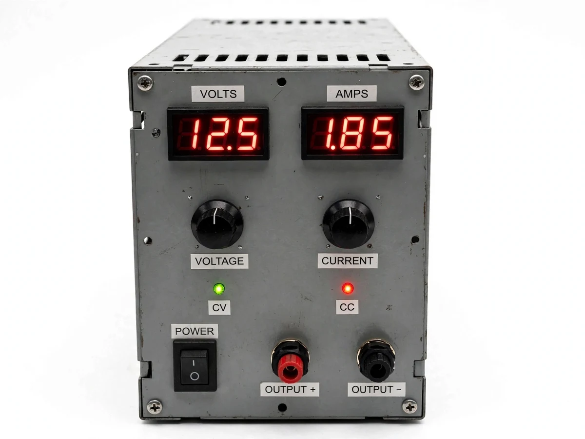
Every electronics lab runs on its bench power supplies, yet most students only ever turn the knobs — they never learn why a linear supply is heavy, why it gets hot at low voltage and high current, or what the current-limit knob actually does to the control loop. Building one answers all of it. This project is the canonical student linear supply: a mains transformer and bridge rectifier feed unregulated DC to a series-pass power transistor driven by an op-amp error amplifier, which holds the output at the knob-set voltage against load changes. A second loop watches the output current and folds the voltage back when the set limit is reached — that is the CC/CV behavior, and it makes the supply inherently short-circuit proof. Digital panel meters show volts and amps, and the enclosure, binding posts and heatsink make it a genuinely usable bench instrument, not a breadboard demo.
How it works
- The mains transformer steps 230 V AC down to the secondary voltage; a bridge rectifier and reservoir capacitor produce unregulated DC with ripple.
- The series-pass transistor sits between the unregulated DC and the output; the op-amp error amplifier compares a divided-down sample of the output against the knob-set reference.
- Any output deviation drives the pass transistor harder or softer, holding the set voltage against load and line changes — the voltage-regulation loop.
- A second op-amp loop senses output current across a shunt resistor; when current reaches the knob-set limit, this loop takes over and pulls the voltage down to hold current constant.
- The CC/CV LEDs show which loop is active: green in normal voltage regulation, red when the current limit is engaged.
- The digital panel meters continuously display output voltage and current, powered from an auxiliary winding.
- Under a short circuit, the current loop clamps the output at the set limit while the pass transistor dissipates the full power — which the heatsink is sized to survive.
Tech stack:
- 230 V to ~24 V mains transformer
- Bridge rectifier + reservoir capacitor
- Series-pass power transistor (2N3055 class) on heatsink
- Op-amp error amplifier (voltage loop)
- Op-amp current-limit loop with shunt sensing
- Digital voltmeter + ammeter panel modules
- Multi-turn potentiometers for V/I setting
- Metal enclosure, binding posts, mains fuse + switch
| Parameter | Value |
|---|---|
| Output voltage | 0–30 V DC adjustable (design) |
| Output current | 0–3 A with adjustable limit (design) |
| Regulation | Line/load regulation per linear design (design target) |
| Ripple | Under approximately 50 mV p-p at full load (design target) |
| Metering | 3-digit LED voltmeter + ammeter (±1% per meter datasheet) |
| Pass device | 2N3055-class transistor on calculated heatsink |
| Protection | Current-limit foldback, mains fuse, thermal sizing |
| Output terminals | 4 mm binding posts + chassis ground |
Project features
- [0–30 V adjustable output] Single-turn or multi-turn voltage knob sweeps the full range via the op-amp reference divider.
- [0–3 A adjustable current limit] Independent current knob sets the limit; exceeding it folds the supply into constant-current mode automatically.
- [CC/CV indicator LEDs] Green LED for constant-voltage, red for constant-current — the supply always tells you which loop is in control.
- [Digital panel meters] 3-digit voltmeter and ammeter modules show output voltage and current simultaneously.
- [Series-pass linear regulation] Power transistor with op-amp error amplifier — the classic topology, fully documented stage by stage.
- [Short-circuit proof] The current-limit loop holds a shorted output at the set current indefinitely; the design is thermally rated for it.
- [Thermal design] Heatsink sized by calculation for worst-case dissipation (low output voltage at full current), with the sizing math in the report.
- [Binding-post outputs] Standard 4 mm safety binding posts (red/black) plus a chassis ground terminal on a labeled front panel.
What is included
- Complete bench supply unit in a ventilated metal enclosure, wired and tested
- Transformer, rectifier, pass transistor on heatsink, control PCB, panel meters
- Heatsink thermal-sizing calculation sheet
- Stage-by-stage circuit explanation (rectifier, regulator, current limit)
- Wiring diagram, front-panel layout and enclosure drawings
- Project report PDF, PPT presentation and viva Q&A document
Limitations & prerequisites
- Linear topology: it is heavy and inefficient by design — at 5 V / 3 A output the pass transistor dissipates roughly 75 W as heat, which is exactly why the thermal design is part of the project.
- No programmable/digital interface — voltage and current are set by manual knobs; remote control is future scope.
- Ripple and regulation figures are design targets; the report includes the measurement procedure (multimeter + the module's own meters) for the student to verify their own build.
- Single output only; dual/tracking supplies are a documented extension, not included.
- Mains wiring inside: the kit is supplied assembled and tested, with a safety note on never opening the enclosure while powered.
Frequently Asked Questions
Why build a linear supply instead of buying a switching one?
Because the learning is the point. A linear supply's every stage — transformer, rectifier, error amplifier, current loop, heatsink — is understandable and measurable by a student. A switching module is a black box with the same knobs.
What do the CC and CV LEDs mean?
CV (green) means the voltage loop is in control and the load draws whatever current it needs. CC (red) means you hit the current limit, so the supply lowered the voltage to hold current constant — normal behavior, not a fault.
Is it really short-circuit proof?
By design, yes: shorting the output just engages the current-limit loop, which holds the set current while the heatsink absorbs the dissipation it was sized for. The kit still recommends sensible current settings.
Why does it get hot at low voltage?
The pass transistor drops the difference between the unregulated DC (about 34 V) and the output. At 5 V / 3 A that is ~29 V × 3 A ≈ 87 W of heat — the fundamental tradeoff of linear regulation, and the reason for the calculated heatsink.
How accurate are the panel meters?
The meter modules are ±1% per their datasheet; the calibration procedure in the kit shows how to trim the voltage setting against a trusted multimeter.
Is this project suitable for a final-year project?
Yes — for Electronics and Electrical programs. It covers rectification, feedback regulation, current limiting, thermal design and mains safety in one genuinely useful instrument. Suitable for B.E./B.Tech final-year projects in Electronics and Electrical engineering.
Components & software requirements
- 230 V to ~24 V mains transformer
- Bridge rectifier + reservoir capacitor
- Series-pass power transistor (2N3055 class) on heatsink
- Op-amp error amplifier (voltage loop)
- Op-amp current-limit loop with shunt sensing
- Digital voltmeter + ammeter panel modules
- Multi-turn potentiometers for V/I setting
- Metal enclosure, binding posts, mains fuse + switch
Delivery information
Built-to-order project. Delivery timeline is shared after order confirmation based on current queue.
Support terms
Complete documentation, setup guide, and viva preparation included. Support for setup and explanation provided.