
More project photos (2)
The problem
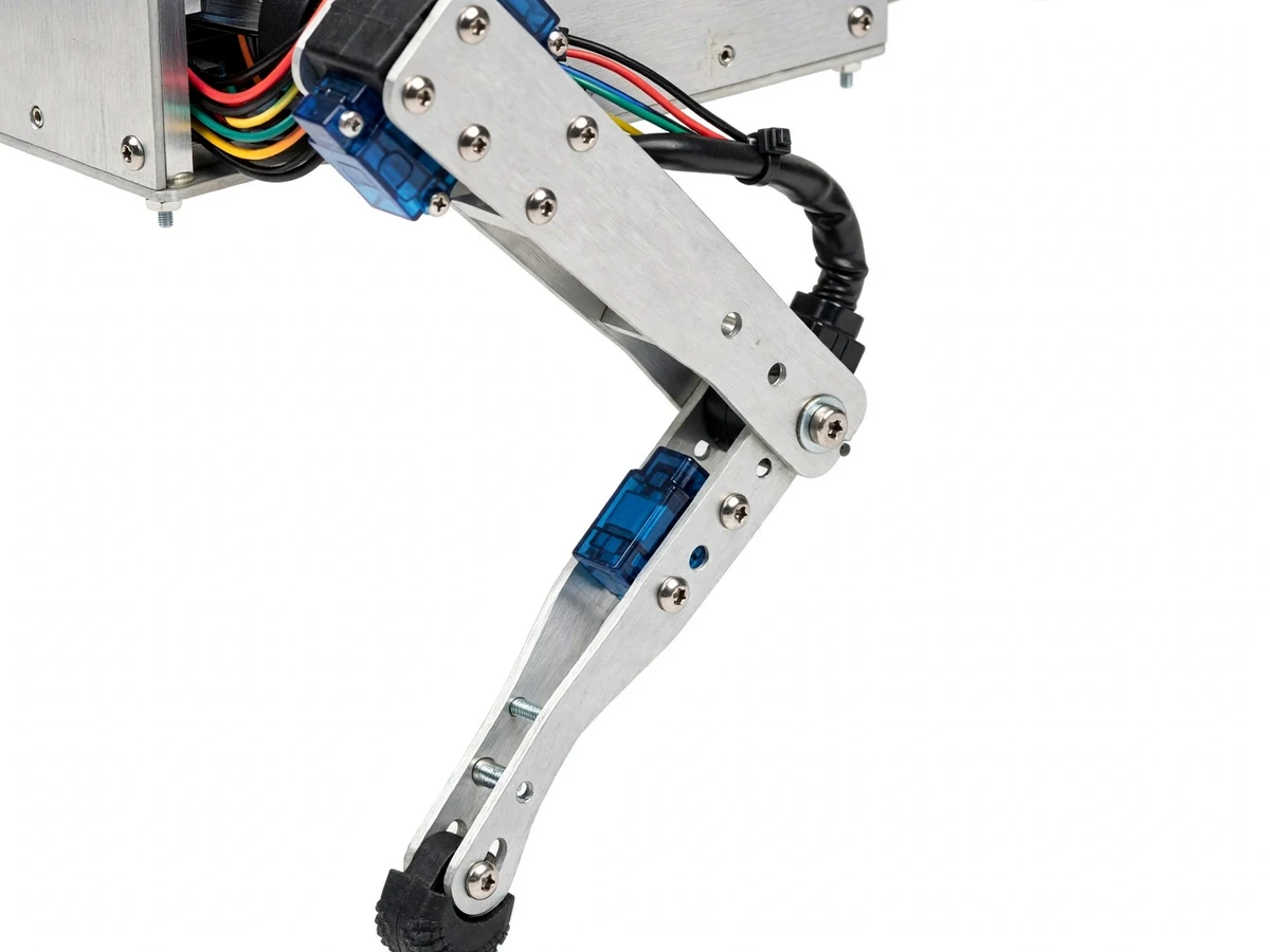
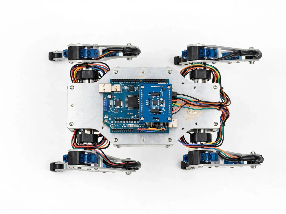
Wheeled robots are easy; legged robots are where robotics gets interesting. A quadruped has to coordinate eight servos in precise phase relationships just to stand, let alone walk — and when students get the timing right, the machine genuinely walks. This project builds a spider-style quadruped: four legs, two servos per leg (hip and knee), an Arduino with a servo driver board generating the PWM signals, and an ultrasonic sensor for obstacle detection. The firmware implements proper gait patterns — a stable wave gait for careful walking and a faster trot — plus turning by differential leg phasing. Bluetooth remote control from a phone app makes it demonstrable and fun, while the engineering underneath (gait tables, servo current budgets, center-of-gravity management) is serious robotics.
How it works
- The Arduino boots the servo driver and moves all eight servos to the neutral standing pose, establishing the robot's balance baseline.
- The selected gait table (wave or trot) defines each servo's angle as a function of the gait phase; the firmware steps the phase forward at the gait frequency.
- In wave gait, legs lift and plant one at a time for maximum stability; in trot, diagonal pairs move together for speed.
- The ultrasonic sensor scans ahead continuously; when an obstacle is within the stop distance, the robot halts and executes a turn sequence.
- Bluetooth commands from the phone override autonomy: walk forward/back, turn left/right, switch gait, or stand at attention.
- A dedicated 5–6 V high-current supply feeds the servos separately from the logic, preventing the brownouts that plague servo projects.
- Students tune stride and timing parameters on their own build using the gait tuning guide, documenting the final gait in the report.
Tech stack:
- Arduino Uno + 16-channel servo driver
- 8x SG90/MG996R-class servos
- Aluminium leg linkages + chassis
- Ultrasonic distance sensor
- HC-05 Bluetooth module
- Phone control app
- 5–6 V high-current servo supply
- Gait sequencing firmware
| Parameter | Value |
|---|---|
| Controller | Arduino Uno + PCA9685-class servo driver — datasheets |
| DOF | 8 (2 servos x 4 legs) |
| Servos | SG90/MG996R class, approximately 2.5–10 kg·cm (datasheet class) |
| Gaits | Wave + trot, phase-timed (firmware) |
| Obstacle range | Ultrasonic, approximately 5–30 cm stop band (expected) |
| Control | Bluetooth HC-05, approximately 10 m (design) |
| Power | 5–6 V servo bus (high current) + logic supply (design) |
| Chassis | Aluminium, approximately 25 cm span (prototype) |
Project features
- [Programmed walk gaits] Wave gait for stable walking and trot gait for speed, implemented as phase-timed servo sequences — real legged locomotion, not random leg wiggling.
- [8-servo leg mechanics] Four legs with hip and knee servos on aluminium linkages, giving the 8-DOF platform that makes gait study meaningful.
- [Ultrasonic obstacle avoidance] Front-mounted ultrasonic sensor triggers stop-and-turn behavior, demonstrating sensor-driven autonomy.
- [Bluetooth remote control] Phone app control for walk, turn, gait select and stop — the standard live-demo interface.
- [Turning by differential phasing] The robot steers by phasing the left and right leg pairs differently, teaching the legged equivalent of differential drive.
- [Servo power design] A dedicated high-current servo supply with the current budget documented, addressing the number-one failure mode of servo robots (brownouts).
- [Gait tuning guide] Step-by-step procedure for adjusting stride length, lift height and phase timing on the student's own build.
What is included
- Quadruped spider robot (assembled: chassis, 8 servos, linkages)
- Arduino + servo driver electronics (programmed)
- Complete gait firmware source code with tuning guide
- Phone control app setup guide
- Wiring diagram and mechanical assembly guide
- Servo power and current-budget document
- Project report PDF (background, gait theory, firmware, results)
- PPT presentation for final review
- Viva Q&A preparation document (gaits, servo control, power design)
Limitations & prerequisites
- This is a servo-driven hobby quadruped, not a dynamic running robot — gaits are quasi-static and speeds are modest, stated honestly.
- Servo quality varies; the tuning guide expects the student to calibrate on their own build rather than trusting nominal angles.
- Battery life is approximately 20–30 minutes of walking (expected); continuous demo needs the supply or spare packs.
- The ultrasonic sensor sees only straight ahead; side and rear obstacles are out of scope.
- Rough or slippery surfaces degrade gait performance — the report documents tested surfaces honestly.
- Bluetooth range is approximately 10 m line-of-sight; walls and interference shorten it.
Frequently Asked Questions
What is a gait, exactly?
A gait is the timed pattern of leg movements — which legs lift, in what order, and how far. The wave gait moves one leg at a time (very stable); the trot moves diagonal pairs together (faster). The firmware stores each as a phase table the servos follow.
How does it turn?
By differential phasing: the legs on one side take longer strides (or a different phase) than the other side, yawing the body around — the legged equivalent of a tank turn.
Why does it need a separate servo power supply?
Eight servos moving together can draw several amps in spikes. Sharing that with the Arduino's supply causes brownouts and resets — the classic servo-robot failure. A dedicated high-current servo bus is the correct engineering answer.
Can it climb stairs or rough ground?
Not reliably — this is a flat-surface walker. The report documents tested surfaces honestly and lists terrain handling as future scope.
How is it controlled?
A phone app over Bluetooth HC-05: walk, turn, gait select and stop. The ultrasonic sensor adds autonomous stop-and-turn when an obstacle appears ahead.
Is this project suitable for a final-year project?
Yes — for Mechanical, Electronics and Electrical programs. Legged locomotion teaches gait kinematics, servo systems and power design far beyond a wheeled robot. Suitable for B.E./B.Tech final-year projects in Mechanical, Electronics and Electrical.
Components & software requirements
- Arduino Uno + 16-channel servo driver
- 8x SG90/MG996R-class servos
- Aluminium leg linkages + chassis
- Ultrasonic distance sensor
- HC-05 Bluetooth module
- Phone control app
- 5–6 V high-current servo supply
- Gait sequencing firmware
Delivery information
Built-to-order project. Delivery timeline is shared after order confirmation based on current queue.
Support terms
Complete documentation, setup guide, and viva preparation included. Support for setup and explanation provided.