
More project photos (2)
The problem
Multirotor drones look simple from the outside — four motors, a frame, a camera — but stable flight is a hard real-time control problem. The craft must measure its own tilt hundreds of times per second and correct every motor continuously, or it flips within a second of takeoff. Students meet this theory as PID equations in control-systems classes, yet rarely see the loop running on real hardware: what the P, I and D terms actually do to flight feel, why every ESC must learn the same throttle endpoints, how diagonal motor pairs cancel torque. Meanwhile, ready-to-fly camera drones are sealed black boxes that teach nothing. This project opens the box. Building an F450-class quadcopter from frame, motors, ESCs, flight controller and FPV gear gives students a working, tuneable control system — one where PID tuning, calibration and pre-flight discipline are learned by doing, not by simulation alone.
How it works
- The pilot's stick inputs travel from the 2.4 GHz transmitter to the onboard receiver, then to the flight controller.
- The flight controller's IMU (gyroscope + accelerometer) measures the drone's actual attitude several hundred times per second.
- A PID control loop compares desired vs. actual attitude and adjusts each motor's speed through its ESC — speeding up motors on the low side to level the craft.
- Diagonal motor pairs spin in opposite directions so torque reactions cancel; yaw is controlled by deliberately unbalancing the pairs.
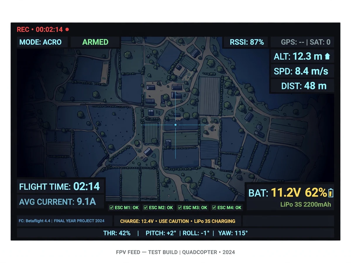
- The FPV camera feeds a 5.8 GHz analog video transmitter, streaming live video to the ground-station monitor with near-zero latency.
- A low-voltage alarm on the LiPo warns the pilot to land before the battery discharges to unsafe levels.
Project features
- F450-class quadcopter frame with integrated power distribution board
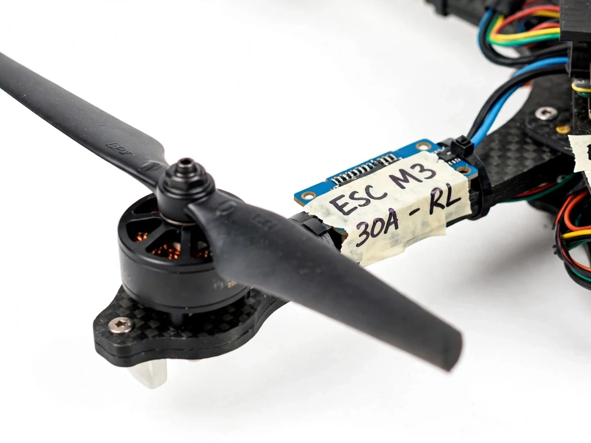
- 4× brushless outrunner motors with 30 A ESCs (throttle endpoints calibrated)
- Gyro + accelerometer flight controller with self-leveling stabilization
- FPV camera with live 5.8 GHz analog video to a ground-station monitor
- 2.4 GHz radio transmitter/receiver for manual flight control
- Stable hover tuning, with PID basics covered in the guide
- 3S LiPo battery with low-voltage alarm for safe flight times
- Safe-flight checklist and pre-flight procedure card
- Modular, labeled wiring so every subsystem can be explained
What is included
- Assembled quadcopter
- Full component list with the exact frame, motors, ESCs and electronics used
- Flight controller configuration file and tuning notes
- ESC calibration and setup guide
- Wiring diagram (power distribution, signal routing)
- PID tuning basics guide — what P, I and D do to flight behavior
- Safe-flight checklist and pre-flight procedure card
- Assembly guide
- Project report PDF (design, control theory, testing, results)
- PPT presentation
- Viva Q&A document
FAQs
- How does the flight controller keep the drone stable? The IMU measures tilt hundreds of times per second. A PID loop computes the error between desired and actual attitude and adjusts each motor's speed — the P term reacts to current error, I corrects persistent drift, D damps oscillation. The tuning guide shows how each term changes flight feel.
- What is ESC calibration and why is it needed? Each ESC must learn the transmitter's full throttle range (min to max pulse). Calibration teaches all four ESCs identical endpoints so the motors spin up evenly — without it, the drone yaws or flips on takeoff.
- Why do two propellers spin clockwise and two counter-clockwise? To cancel torque reaction: each motor's spin tries to rotate the frame the opposite way. Diagonal pairs spin the same direction, so net torque is zero and the drone doesn't spin. Yaw control comes from deliberately unbalancing the pairs.
- What are the DGCA drone rules I should know? India's DGCA classifies drones by weight; sub-250 g "nano" drones have the lightest requirements, while this F450-class build typically falls in the micro category. Rules evolve — check the DigitalSky platform for current registration and permission requirements, and always fly in open, permitted areas.
- Is it safe to demo this at college? Only outdoors in a large open ground, away from people and buildings, with the safe-flight checklist followed and a faculty supervisor present. Indoor or crowded-area flight is not acceptable. Many colleges approve a tethered or low-altitude hover demo — discuss with your guide first.
- How is the live video transmitted? The onboard FPV camera feeds a 5.8 GHz analog video transmitter; a ground-station receiver displays it on a monitor in real time with near-zero latency — the same technology used in FPV racing drones.
Limitations & prerequisites
- Typical all-up weight (800 g–1.2 kg) places this build in the DGCA micro category, not nano — check current DigitalSky requirements before flying; regulations change and the operator is responsible for compliance.
- Fly only in open areas, away from people, buildings, airports and restricted zones; never fly over crowds.
- Analog FPV range is limited (typically a few hundred meters with clear line of sight) and subject to interference.
- Flight time is 8–12 minutes per battery; wind significantly reduces endurance and stability.
- LiPo batteries demand careful handling — always balance-charge, never puncture, store at storage voltage.
- This is an educational build, not a certified commercial UAV; it is not suitable for beyond-visual-line-of-sight or commercial operations.
Components & software requirements
- F450 frame kit with power distribution board
- 4× brushless outrunner motors (~1000 KV) + 10" propellers (CW/CCW pairs)
- 4× 30 A ESCs (SimonK/BLHeli), throttle-endpoint calibrated
- Flight controller with 6-axis IMU (gyro + accelerometer), PID stabilization
- FPV camera + 5.8 GHz video transmitter; ground-station receiver/monitor
- 6-channel 2.4 GHz radio transmitter and receiver
- 3S LiPo battery (2200–5200 mAh) with balance charger and low-voltage alarm
- PID tuning and safe-flight documentation
Specifications
| Parameter | Value |
|---|---|
| Frame | F450, ~450 mm motor-to-motor diagonal |
| Motors | 4× brushless outrunner, ~1000 KV |
| ESCs | 4× 30 A, throttle-endpoint calibrated |
| Flight controller | 6-axis IMU (gyro + accelerometer), PID stabilization |
| Video | FPV camera, 5.8 GHz analog TX, live ground-station feed |
| Radio link | 2.4 GHz, 6 channels |
| Battery | 3S LiPo (11.1 V), 2200–5200 mAh, balance-charged |
| Flight time | ~8–12 min (payload and wind dependent) |
| Takeoff weight | ~800 g – 1.2 kg (configuration dependent) |
| Control loop | PID attitude stabilization, several-hundred-Hz IMU fusion |