
More project photos (3)
The problem
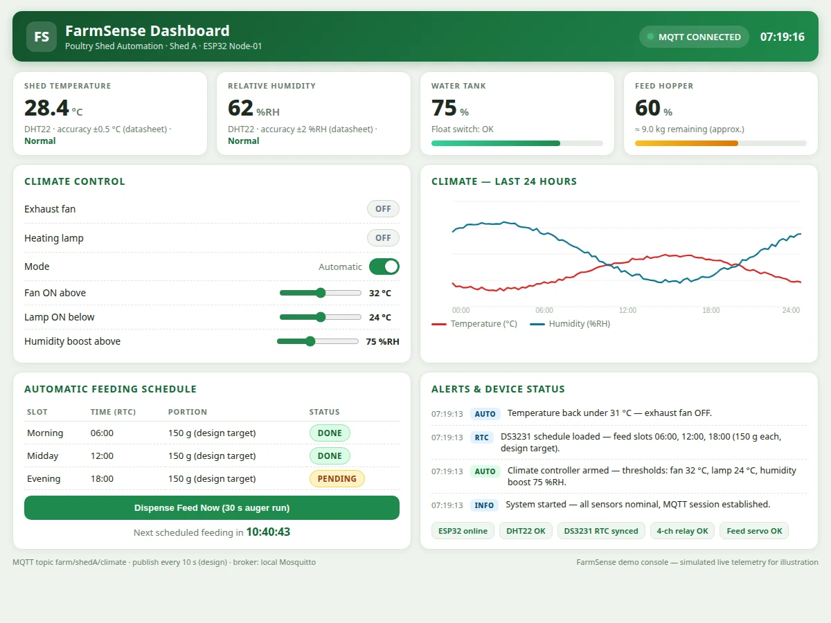
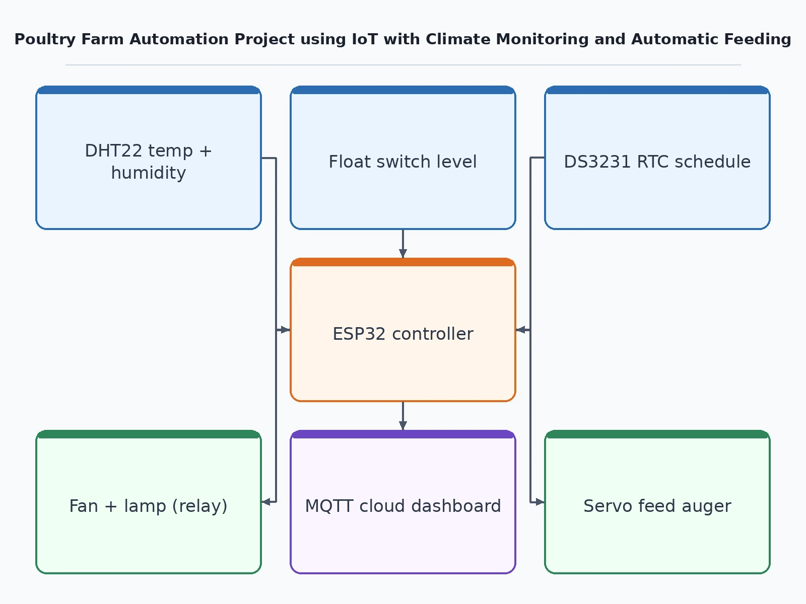
A poultry shed is unforgiving: a hot afternoon can push indoor temperature past safe limits in under an hour, and missed or irregular feeding directly slows bird growth. Small and mid-size farms cannot watch the shed all day, and manual routines — checking a wall thermometer, flipping the fan switch, carrying feed at fixed hours — slip whenever labour is short. This project automates the two jobs that matter most. An ESP32 controller continuously reads shed temperature and humidity from a DHT22 sensor and drives an exhaust fan and a heating lamp through a relay module against configurable thresholds, so the climate stays inside the comfort band without manual switches. Separately, a DS3231 real-time clock triggers a servo-driven feed auger three times a day with a fixed portion per slot, and a float switch raises an alert when the water tank runs low. All of it is visible on an MQTT cloud dashboard — live climate graphs, feed schedule, hopper and tank levels, and a timestamped alert log — so the owner can supervise the shed from a phone.
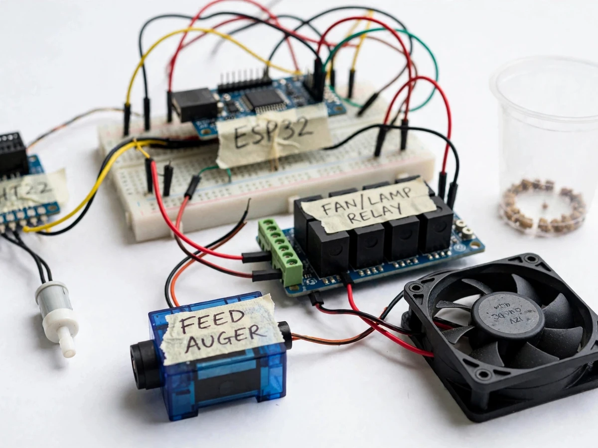
DHT22 reads shed temperature and humidity every 2 seconds; a float switch reports the water tank level.
Follow the working sequence
How it works
- The DHT22 sensor measures shed temperature and humidity; the ESP32 reads it every 2 seconds (design target).
- Readings are compared against stored thresholds: above 32 °C the exhaust fan relay closes, below 24 °C the heating lamp relay closes, each with 1 °C hysteresis to avoid chattering.
- The DS3231 RTC fires feeding slots at 06:00, 12:00 and 18:00; the servo-driven auger runs a timed 30-second dispense of roughly 150 g per slot (design target).
- A float switch reports the water tank state; a low level generates an immediate dashboard alert.
- Every 10 seconds (design target) the ESP32 publishes temperature, humidity, device states and levels to the MQTT broker under the farm/shedA topic tree.
- The web dashboard subscribes to these topics and renders live graphs, schedule status and the alert log; threshold changes and manual commands travel back over MQTT.
- On power-up the ESP32 restores thresholds and the schedule from flash and resumes automatic control within seconds.
Tech stack:
- ESP32 (firmware in C/C++ on the Arduino framework)
- DHT22 temperature/humidity sensor
- 4-channel relay module · DS3231 RTC
- Servo-driven feed auger · float switch
- MQTT (Mosquitto broker)
- HTML/CSS/JavaScript cloud dashboard
- 12 V DC power supply
| Parameter | Value |
|---|---|
| Controller | ESP32-WROOM-32, 240 MHz dual-core, Wi-Fi + Bluetooth (datasheet) |
| Temperature sensing | DHT22, ±0.5 °C accuracy, −40 to 80 °C range (datasheet) |
| Humidity sensing | DHT22, ±2 %RH accuracy, 0 to 100 %RH range (datasheet) |
| Climate control | Relay-driven exhaust fan + heating lamp, adjustable thresholds (design) |
| Fan trigger | Above 32 °C, 1 °C hysteresis (design target, adjustable) |
| Lamp trigger | Below 24 °C, 1 °C hysteresis (design target, adjustable) |
| Feeding schedule | 3 slots/day (06:00, 12:00, 18:00) via DS3231 RTC (design) |
| Feed portion | Approximately 150 g per dispense (design target, auger-dependent) |
| Auger run time | 30 s per dispense (design target, adjustable in firmware) |
| Water monitoring | Float switch with low-level dashboard alert (design) |
| Cloud telemetry | MQTT publish every 10 s (design target) |
| Power | 12 V DC, approximately 2 A adapter (expected) |
| Dashboard | Single-file web app, runs in phone/laptop browser (expected) |
Project features
- [DHT22 climate sensing] The ESP32 polls shed temperature and humidity from a DHT22 sensor, which carries datasheet accuracies of ±0.5 °C and ±2 %RH — honest, documented sensing rather than guessed values.
- [Automatic fan and heating control] A relay module switches an exhaust fan on above the high-temperature threshold and a heating lamp on below the low-temperature threshold, both with 1 °C hysteresis and adjustable setpoints.
- [RTC-scheduled automatic feeding] A DS3231 real-time clock keeps the feeding timetable even when Wi-Fi is down; the servo-driven auger dispenses at three daily slots with a repeatable portion per run.
- [Water tank level watch] A float switch monitors the drinker/water tank and the dashboard raises a low-level alert, so birds are never left without water unnoticed.
- [MQTT cloud dashboard] Live climate graphs, device states, feed schedule, tank and hopper levels and a timestamped alert log stream to a web dashboard over MQTT, viewable on any phone or laptop browser.
- [Manual override mode] Automatic control can be switched to manual from the dashboard, so fan, lamp and feed can be driven by hand during demonstrations and viva.
- [Offline-safe local control] Thresholds and the feeding schedule live in the ESP32's flash, so climate control and feeding continue during a Wi-Fi outage; only the remote dashboard pauses.
- [Configurable thresholds] Fan, lamp and humidity-boost setpoints are adjustable from the dashboard without reflashing firmware.
What is included
- Assembled and wired prototype (ESP32, DHT22, relay module, servo auger, float switch, fan)
- Complete ESP32 firmware source with threshold and schedule configuration
- Circuit and wiring diagram with component list
- MQTT cloud dashboard web app
- Project abstract PDF
- Project report PDF (background, methodology, architecture, results, limitations)
- PPT presentation for final review
- Viva Q&A preparation document (sensors, relays, MQTT, scheduling)
Limitations & prerequisites
- The DHT22 reads ±0.5 °C per its datasheet — adequate for shed comfort bands, not a replacement for calibrated veterinary thermometry.
- Feed portion is a design target (~150 g per 30 s run); actual grams depend on auger geometry and pellet size, so the buyer calibrates by weighing output.
- The prototype models one shed zone; scaling to a full farm needs additional sensor nodes per zone.
- Relay outputs switch demo-scale loads — mains wiring for real fans or heaters must be done by the buyer under qualified supervision.
- The cloud dashboard needs Wi-Fi; local climate control and feeding continue offline, but remote alerts pause.
- Feed hopper refilling is manual; the dashboard shows the level but cannot refill itself.
- This is a shed-management prototype — it does not detect disease or replace veterinary care.
Frequently Asked Questions
Which controller is used and why?
The ESP32. It has built-in Wi-Fi for the MQTT cloud link, enough GPIOs for the DHT22, relay module, servo and float switch, and flash memory to keep thresholds and the feeding schedule across power cuts. An Arduino would need an extra Wi-Fi module for the same job.
Does the system work without Wi-Fi?
Yes for the core jobs. The feeding timetable and climate thresholds live in the ESP32's flash with the DS3231 RTC, so fan, lamp and feeder keep working during an outage. Only the remote dashboard and push alerts pause until the network returns.
How is the feed portion calibrated?
Each scheduled slot runs the servo auger for 30 seconds, a design target of roughly 150 g. Actual grams depend on the auger and pellet size, so the buyer weighs one dispense and adjusts the run time in firmware — the report documents this calibration procedure.
Can sensors or actuators be changed?
Yes. Extra DHT22 nodes can cover more shed zones, and the relay outputs can drive a misting pump instead of a heating lamp for summer cooling. A buzzer can be added for on-site alarms, and GSM or LoRa can be fitted as an optional customization where farm Wi-Fi is unavailable.
Is this project suitable for a final-year project?
Yes — for IoT & Embedded, Electronics and Electrical programs. It demonstrates sensor interfacing, closed-loop relay control with hysteresis, real-time scheduling on an RTC, MQTT telemetry and a working cloud dashboard in one coherent build, with clear calibration and limitation discussions for the viva.
Components & software requirements
- ESP32 (firmware in C/C++ on the Arduino framework)
- DHT22 temperature/humidity sensor
- 4-channel relay module · DS3231 RTC
- Servo-driven feed auger · float switch
- MQTT (Mosquitto broker)
- HTML/CSS/JavaScript cloud dashboard
- 12 V DC power supply
Delivery information
Built-to-order project. Delivery timeline is shared after order confirmation based on current queue.
Support terms
Complete documentation, setup guide, and viva preparation included. Support for setup and explanation provided.
Download free synopsis (PDF)
Enter your name and email — the synopsis PDF downloads immediately. We may send occasional project updates; no spam, unsubscribe anytime.