
More project photos (2)
The problem
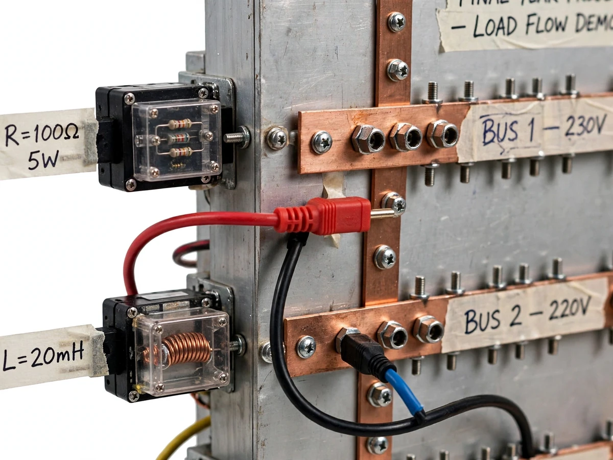
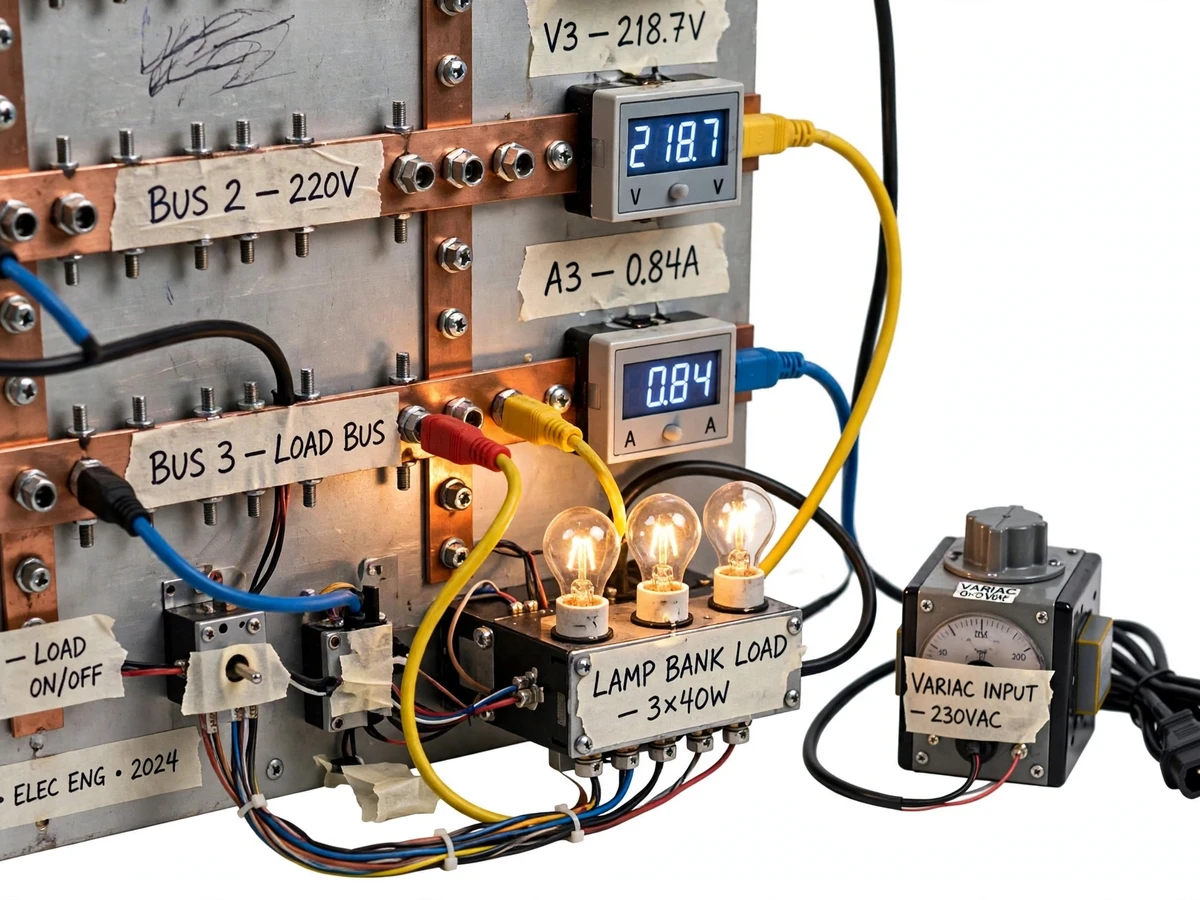
Load-flow analysis is usually pure software — buses and branches solved by Newton-Raphson on a screen, with the physical meaning buried under matrices. Before digital computers, power engineers studied the same problems on AC network analyzers: scaled physical models of power systems where you could plug in a line, switch a load and watch the power flow change. This project revives that approach as a bench-top teaching panel: a low-voltage scaled AC network with plug-in R/X impedance modules, busbar nodes with digital panel meters, a variac-fed source representing the grid, and lamp-bank load modules (resistive and inductive). Reconfiguring the topology with patch cords, adding loads, or switching in capacitor banks produces immediate, visible changes in bus voltages and branch currents — the concepts of voltage drop, reactive power flow and compensation become something students can touch.
How it works
- The variac-fed source energizes the scaled network at a safe low AC voltage representing the grid infeed.
- Students plug impedance modules into the panel to build a feeder — radial first, then ring or multi-feeder with patch cords.
- Load modules are plugged in at chosen buses; the bus meters immediately show the voltage profile sagging along the feeder.
- Branch current meters reveal how power flow redistributes when the topology changes from radial to ring.
- Switching in the capacitor bank shows reactive compensation: power factor improves and bus voltages recover.
- The manual's per-unit scaling section maps every measured value back to the high-voltage system being modelled.
Tech stack:
- Plug-in R/X impedance branch modules
- Busbar panel with patch-cord topology
- Variac-fed scaled AC source with per-unit scaling
- Digital panel meters (bus voltage, branch current)
- Lamp-bank load modules (resistive + inductive)
- Switchable capacitor bank for compensation demo
| Parameter | Value |
|---|---|
| Network | 4–6 bus scaled AC network with plug-in topology |
| Voltage level | Low-voltage scaled representation (12–24 V AC) of HV feeders |
| Branches | Plug-in R/X impedance modules, fused per branch |
| Source | Variac-fed; per-unit scaling explained in the manual |
| Metering | Digital panel meters per bus (voltage, current) |
| Loads | Lamp-bank load modules, resistive and inductive |
| Compensation | Switchable capacitor bank |
Project features
- [Plug-in impedance branches] R/X branch modules plug into the panel to represent transmission lines and feeders with different impedances.
- [Metered bus nodes] Every busbar node carries digital panel meters for voltage and current, so the voltage profile across the network reads directly.
- [Reconfigurable topology] Patch cords rewire the network between radial, ring and multi-feeder layouts in minutes.
- [Plug-in load modules] Lamp-bank loads — resistive and inductive — plug in at any bus to represent consumer demand.
- [Capacitor compensation demo] A switchable capacitor bank demonstrates reactive power compensation and its effect on voltage profile and power factor.
- [Per-unit scaling concept] The variac-fed low-voltage network models high-voltage feeders through explained per-unit scaling, documented in the manual.
- [Fused branch protection] Each branch is fused, so short-circuit and overload demonstrations stay safe.
What is included
- Working analog network panel with impedance, load and capacitor modules
- Patch cords, busbar hardware and fused branch holders
- Wiring documentation, component list and per-unit scaling manual
- Experiment procedure (radial vs ring, loading, compensation studies)
- Project report PDF (load-flow theory, analog modelling, experiment formats)
- PPT presentation for final review
- Viva Q&A preparation document (power flow, voltage drop, reactive compensation, per-unit system)
- Setup and safety guide
Limitations & prerequisites
- This is an analog scaled model — it builds physical intuition for load flow but does not replace digital load-flow software (Newton-Raphson, MATPOWER-style tools) for exact solutions.
- Component tolerances in the plug-in modules limit quantitative accuracy; the panel demonstrates trends and relationships, not precision results.
- The network models high-voltage feeders at safe low voltage through per-unit scaling — the scaling concept must be understood for the readings to be meaningful.
- Topology changes are manual (patch cords); automated switching and SCADA-style control are possible customizations.
- All demonstration readings are taken by the student during the experiments; no network results are pre-claimed.
Frequently Asked Questions
Is this a software load-flow tool?
No — it is a physical analog network. You plug in impedance branches, connect loads and reconfigure topology with patch cords, and read power-flow behaviour directly off the bus meters.
How does a low-voltage panel model a high-voltage system?
Through per-unit scaling, documented in the manual: every measured voltage, current and impedance maps to the modelled HV system by the chosen base values.
What experiments can it demonstrate?
Radial vs ring topology comparison, voltage drop along feeders under loading, reactive power flow, capacitor compensation and the effect of load power factor.
What are the main limitations?
Analog model — trends and intuition, not exact digital solutions; component tolerances limit accuracy; manual reconfiguration; readings are taken by the student, not pre-claimed.
What power supply is needed?
A standard 230 V AC outlet feeds the variac, which steps down to the panel's safe low-voltage operating level.
Is this project suitable for a final-year project?
Yes — for Electrical Engineering programs. It demonstrates power systems analysis, per-unit modelling, reactive compensation and experimental method on hardware students can rewire themselves. Suitable for B.E./B.Tech final-year projects in Electrical Engineering.
Components & software requirements
- Plug-in R/X impedance branch modules
- Busbar panel with patch-cord topology
- Variac-fed scaled AC source with per-unit scaling
- Digital panel meters (bus voltage, branch current)
- Lamp-bank load modules (resistive + inductive)
- Switchable capacitor bank for compensation demo
Delivery information
Built-to-order project. Delivery timeline is shared after order confirmation based on current queue.
Support terms
Complete documentation, setup guide, and viva preparation included. Support for setup and explanation provided.