
More project photos (2)
The problem
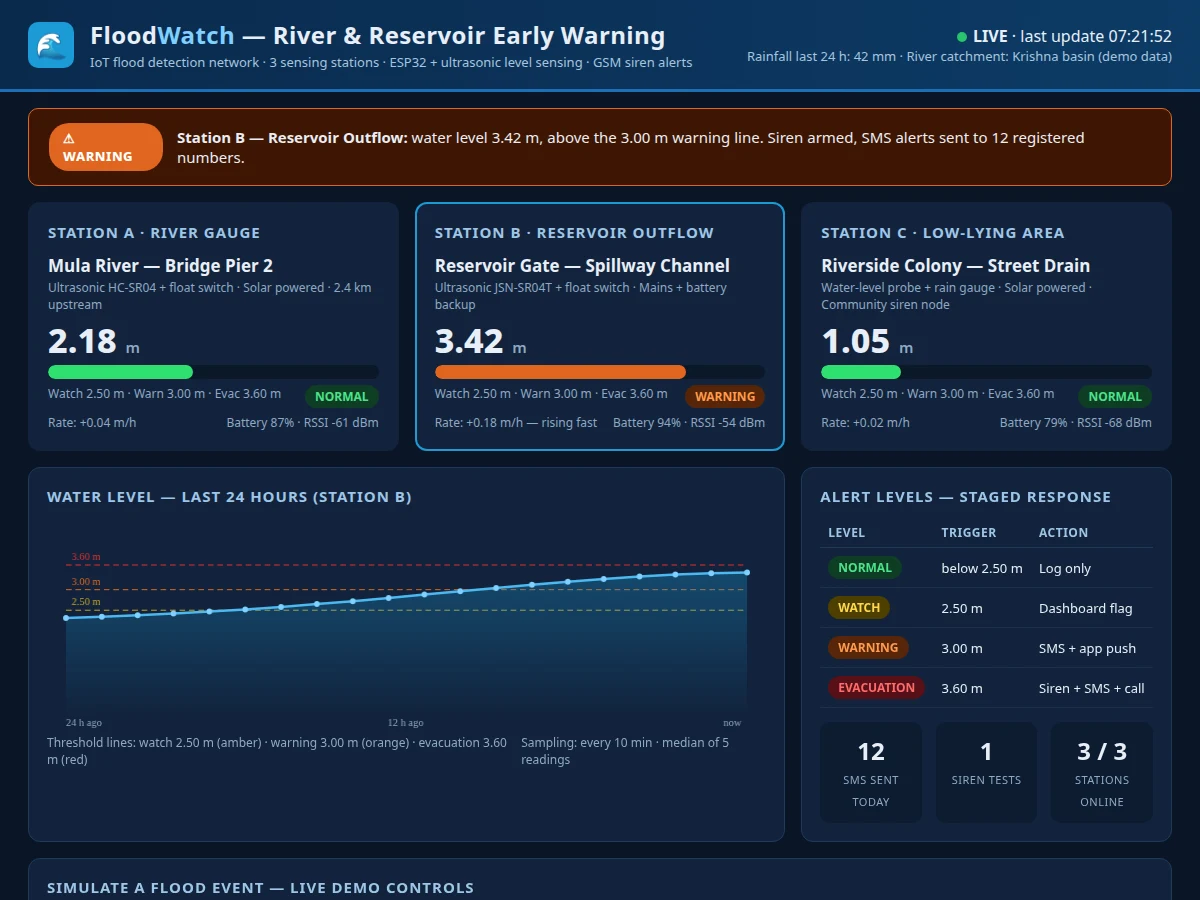
Rivers and reservoirs can rise metres in a few hours during heavy rain, yet most riverside settlements learn about the danger only when water is already at their doorstep. Manual gauge reading is slow and happens at fixed times, so a rapid overnight rise between readings goes unnoticed until streets and homes flood. This project builds an IoT flood detection and early-warning system that watches the water level continuously at three points — a river gauge, a reservoir outflow and a low-lying residential drain — using ESP32 controllers with ultrasonic and float sensors. Each node compares its reading against three staged thresholds (watch 2.50 m, warning 3.00 m, evacuation 3.60 m, all configurable design targets) and pushes the level to a public dashboard every 10 minutes. Crossing a threshold triggers the matching response: a dashboard flag, SMS and app alerts, or the community siren. The system gives residents warning time measured in hours rather than minutes.
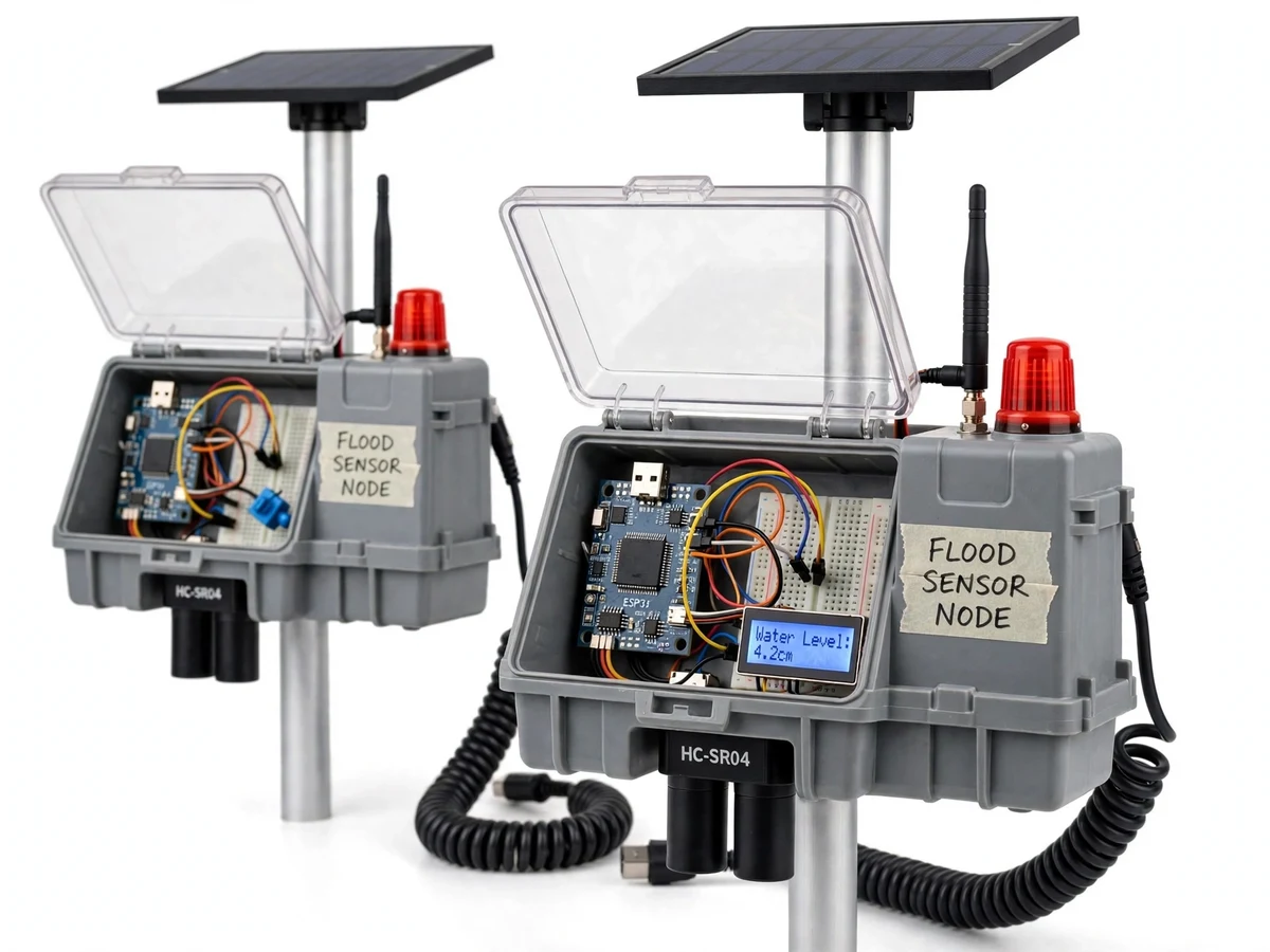
Ultrasonic sensor and float switch measure the level at three stations
Follow the working sequence
How it works
Water-level data travels from the river to a resident's phone in five stages. Each sensor node hangs its ultrasonic sensor above the water and measures the distance to the surface, converting it to a water level; a stilling-well pipe around the sensor damps wave ripples so the reading stays steady. The ESP32 on the node takes 5 readings, keeps the median, and checks the result against the float switch and the three staged thresholds. The node then sends the level over Wi-Fi to the cloud dashboard every 10 minutes, or immediately when a threshold is crossed, and the GSM module takes over for SMS alerts where Wi-Fi is unavailable. The dashboard plots the level against the threshold lines, and the alert logic fires the matching response — flag, SMS, or siren — while writing every crossing to the event log.
- The ultrasonic sensor mounted above the maximum flood line measures the distance to the water surface, and the ESP32 converts the distance into a water level.
- A float switch at the warning level independently confirms the ultrasonic reading, and the node keeps the median of 5 samples to reject wave noise.
- The ESP32 compares the level with the three staged thresholds (Watch 2.50 m, Warning 3.00 m, Evacuation 3.60 m) and shortens the sampling interval when the level is rising.
- Readings are sent over Wi-Fi to the cloud dashboard every 10 minutes, or immediately when a threshold is crossed.
- The dashboard plots the live level and the 24-hour trend against the threshold lines and records every crossing in the event log.
- On a Warning crossing, the SIM800L GSM module sends SMS alerts to the registered numbers; on an Evacuation crossing, the community siren also sounds and app push alerts go out.
- The river and street nodes keep running on solar power with battery backup, so monitoring continues through storm-related power cuts.
Tech stack:
- ESP32 DevKit with Arduino IDE firmware
- HC-SR04 ultrasonic sensor · JSN-SR04T waterproof variant
- Float switch · water-level probe
- SIM800L GSM module for SMS alerts
- 10 W solar panel · 18650 battery backup
- Wi-Fi 802.11 b/g/n · Firebase Realtime Database
- HTML · CSS · JavaScript dashboard
- 12 V community siren · relay driver
| Parameter | Value |
|---|---|
| Controller | ESP32 DevKit, dual-core Xtensa LX6 up to 240 MHz, Wi-Fi 802.11 b/g/n (datasheet values) |
| Water-level sensing | HC-SR04 ultrasonic, 2–400 cm range, 40 kHz, 5 V supply (datasheet values); JSN-SR04T waterproof variant at the reservoir node |
| Backup sensing | Float switch, normally-open contact, confirms the ultrasonic reading at the warning level |
| Sensing nodes | 3 (river gauge, reservoir outflow, low-lying drain) |
| Alert thresholds | Watch 2.50 m, Warning 3.00 m, Evacuation 3.60 m (configurable design targets) |
| Sampling | Every 10 minutes; median of 5 readings per sample (design target) |
| Communication | Wi-Fi 802.11 b/g/n to the cloud dashboard; SIM800L quad-band GSM (850/900/1800/1900 MHz) for SMS fallback (datasheet values) |
| Alert outputs | 12 V siren, SMS via GSM, dashboard flag, app push notification |
| Power | 10 W solar panel with 18650 battery backup at the river and street nodes (design target) |
| Dashboard | Single-file HTML/CSS/JS app: live levels, 24-hour chart, staged alert table, event log |
Project features
The system is built around four capabilities that work together: continuous water-level sensing at three separate points, staged alert thresholds that escalate the response as the water rises, two independent communication paths (Wi-Fi to the dashboard and GSM for SMS), and a public dashboard that shows every station's live level, its 24-hour trend and the full event log. The sensing uses an ultrasonic sensor as the primary measurement with a float switch as an independent cross-check, so a single faulty reading cannot trigger a false alarm. The siren at the low-lying station gives people without phones a warning they can hear, and the solar panel with battery backup keeps the river and street nodes running when mains power is unavailable. Every threshold, sampling interval and alert recipient is configurable in the firmware, so the same build adapts to a campus tank, a village stream or a reservoir outflow without hardware changes.
- [Three-point water-level sensing] Three ESP32 nodes watch a river gauge, a reservoir outflow and a low-lying street drain, each with an ultrasonic sensor and a float switch, so the system sees a flood developing upstream before it reaches homes.
- [Staged alert thresholds] Four levels — Normal, Watch, Warning and Evacuation — at 2.50 m, 3.00 m and 3.60 m (configurable design targets), so the response escalates from a dashboard flag to SMS alerts to the community siren.
- [Dual-sensor cross-check] Every level reading pairs the ultrasonic measurement with a float-switch confirmation, and each sample is the median of 5 readings, which suppresses wave noise and single bad echoes.
- [Siren, SMS and app alerts] Crossing the warning line sends SMS messages through the SIM800L GSM module; crossing the evacuation line also sounds the community siren and triggers app push alerts.
- [Live public dashboard] A web dashboard shows all three stations' current levels, rates of rise, a 24-hour level chart with threshold lines, and an event log of every threshold crossing.
- [Solar power with battery backup] The river and street nodes run from a 10 W solar panel with an 18650 battery (design target), so monitoring continues through power cuts during storms.
- [Rainfall-aware monitoring] A rain gauge at the low-lying station records rainfall, so a sharp rise in rain is visible on the dashboard before the water level itself starts climbing.
What is included
- Three assembled sensor nodes (ESP32, ultrasonic sensor, float switch, siren at the street node, solar panel and battery where specified)
- Complete ESP32 firmware with threshold logic, median filtering and GSM fallback
- Live web dashboard with station cards, 24-hour level chart, alert table and event log
- Circuit diagrams, wiring documentation and component list
- Threshold configuration guide (how to set Watch/Warning/Evacuation levels for a local river or tank)
- Project report PDF (background, methodology, architecture, results from the demo build)
- PPT presentation for final review
- Viva Q&A preparation document (ultrasonic ranging, threshold logic, GSM vs Wi-Fi, calibration)
Limitations & prerequisites
- The HC-SR04 is not waterproof, so the river node must be sheltered and the sensor mounted above the maximum flood line; the reservoir node uses the waterproof JSN-SR04T variant instead.
- Ultrasonic readings are affected by heavy rain, foam and floating debris on the water surface; the median-of-5 filter and the float-switch cross-check reduce, but do not remove, these errors.
- SMS alerts need GSM network coverage and a valid SIM with balance; in a network dead zone only the siren and dashboard flag work.
- Thresholds are site-specific design targets — the 2.50/3.00/3.60 m values suit the demo tank and must be recalibrated for a real river gauge before deployment.
- The prototype is an academic early-warning demonstrator, not a certified disaster-management system, and it does not replace official flood warnings.
- Solar charging depends on daylight; several consecutive overcast days shorten the battery-backed runtime of the river and street nodes.
Frequently Asked Questions
How does the system detect a flood before it reaches homes?
It watches the water level continuously at three points upstream and downhill — a river gauge, a reservoir outflow and a low-lying drain — instead of waiting for water to arrive. Each node compares its level against staged thresholds every 10 minutes, so a rising river triggers a Watch and then a Warning while the water is still upstream, giving residents hours of lead time rather than minutes.
Which controller and sensors are used?
An ESP32 DevKit at each of the three nodes, with an HC-SR04 ultrasonic sensor as the primary level measurement (2–400 cm range, 40 kHz, datasheet values) and a float switch as an independent cross-check. The reservoir node uses the waterproof JSN-SR04T variant, and a SIM800L GSM module sends the SMS alerts.
What happens at each alert level?
The response escalates in four stages: below 2.50 m the system only logs readings, at 2.50 m it raises a Watch flag on the dashboard, at 3.00 m it sends SMS alerts to all registered numbers plus an app push, and at 3.60 m it also sounds the community siren so people without phones are warned too. All three thresholds are configurable for the installation site.
Does it work without internet or during a power cut?
The SMS alerts work over GSM without any internet connection, and the siren is driven locally by the node, so warnings still go out if Wi-Fi fails. The river and street nodes run on a 10 W solar panel with an 18650 battery backup (design target), so monitoring continues through storm-related power cuts, though the cloud dashboard itself needs internet to view remotely.
How is this different from a single underpass water alert?
An underpass alert watches one flooded spot and warns drivers already near it, while this system watches a whole catchment at three points — river, reservoir outflow and low-lying streets — with staged Watch, Warning and Evacuation levels, a community siren and a public dashboard. It warns residents before floodwater reaches their area rather than after.
Is this project suitable for a final-year project?
Yes — for Electronics, Electrical, E&TC and IoT programs, because it demonstrates ultrasonic sensing, embedded threshold logic, GSM and Wi-Fi communication, solar power management and a live dashboard in one working system, with clear calibration and testing work for the report and viva.
Components & software requirements
- ESP32 DevKit with Arduino IDE firmware
- HC-SR04 ultrasonic sensor · JSN-SR04T waterproof variant
- Float switch · water-level probe
- SIM800L GSM module for SMS alerts
- 10 W solar panel · 18650 battery backup
- Wi-Fi 802.11 b/g/n · Firebase Realtime Database
- HTML · CSS · JavaScript dashboard
- 12 V community siren · relay driver
Delivery information
Built-to-order project. Delivery timeline is shared after order confirmation based on current queue.
Support terms
Complete documentation, setup guide, and viva preparation included. Support for setup and explanation provided.
Download free synopsis (PDF)
Enter your name and WhatsApp number — the synopsis PDF downloads immediately. We may send occasional project updates on WhatsApp; no spam.