
More project photos (2)
The problem
The IoT Classroom Noise Level Monitor with LED Alert Board and Logged Readings continuously measures classroom sound level, flashes a visible LED warning when the room stays too loud, and logs every reading to a web dashboard. Teachers currently manage noise by voice and feel — there is no shared, objective reference, so 'too loud' means something different to every teacher and every class. The build answers this with an ESP32 reading a MAX4466 electret microphone module, an 8×8 LED matrix alert board the whole class can see, and MQTT logging to a dashboard with a live gauge, a 60-second chart and a timestamped alert log. One builder insight matters for every buyer: the sensor's raw ADC output is linear voltage but decibels are logarithmic, so the firmware maps readings on a log scale and calibrates once against a phone SPL meter at 1 m — without that step the board shows relative loudness bands, not real dB.
How it works
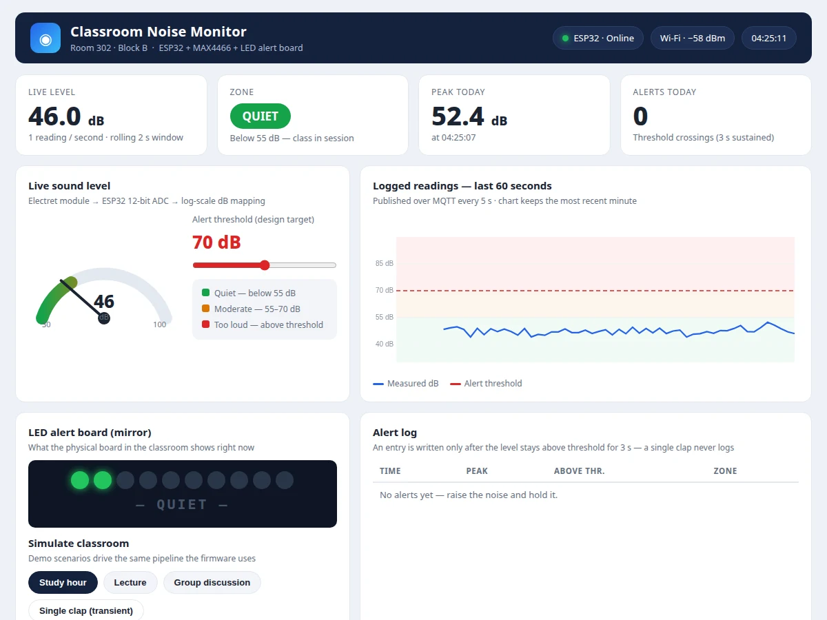
The full chain works like this: the MAX4466 electret microphone module turns classroom sound pressure into an analog voltage, the ESP32 samples it on its 12-bit ADC at about 2 Hz and converts each reading to decibels on a log scale — doubling the sound pressure adds 6 dB, so the firmware works in log space, not raw counts. One calibration against a phone SPL meter at 1 m anchors the scale to real dB. The level is checked against a 70 dB design-target threshold with a 3-second persistence filter: a dropped book never fires an alert, sustained chatter does. On alert, the 8×8 LED matrix scrolls 'TOO LOUD' in the red zone and the dashboard logs a timestamped entry. Every 5 seconds the ESP32 publishes the reading over Wi-Fi via MQTT, and the dashboard redraws its live gauge, 60-second chart and alert log. The LED board and threshold logic run fully offline; only cloud logging pauses without Wi-Fi.
- The MAX4466 electret module converts sound pressure into an analog voltage, with gain adjustable 25×–125× via its onboard potentiometer (datasheet values).
- The ESP32 samples the module output on its 12-bit ADC (0–4095, datasheet) at about 2 Hz and keeps a rolling 2-second peak window.
- Firmware maps the window peak to decibels on a log scale, anchored by a one-time buyer calibration against a phone SPL meter at 1 m.
- The dB value is compared against the 70 dB threshold (design target); the alert fires only after 3 sustained seconds above it (design target).
- On alert, the 8×8 matrix scrolls 'TOO LOUD' in the red zone, the tri-color strip lights red, and the dashboard records a timestamped entry.
- Every 5 seconds (design target) the ESP32 publishes the reading over 2.4 GHz Wi-Fi via MQTT; the dashboard redraws its gauge, chart and log.
Tech stack:
- ESP32 (dual-core 240 MHz · 12-bit ADC)
- MAX4466 electret microphone amplifier module
- 8×8 LED matrix (MAX7219) · tri-color zone LEDs
- Arduino IDE (C++ firmware)
- MQTT (cloud logging)
- HTML · CSS · JavaScript (web dashboard)
- Solderless breadboard prototyping
- USB 5 V power
| Parameter | Value |
|---|---|
| Controller | ESP32 DevKit V1 — dual-core 240 MHz, 12-bit ADC 0–4095 (datasheet values) |
| Sound sensor | MAX4466 electret module — 2.4–5.5 V supply, gain 25×–125× adjustable, analog output (datasheet values) |
| Alert bands | <55 dB quiet / 55–70 dB moderate / >70 dB alert (design targets, configurable) |
| Sampling | ADC read at ~2 Hz; dB from rolling 2-second peak window (design target) |
| Alert latency | <3 s from sustained over-threshold to LED + log (design target) |
| Calibration | One-time, against a phone SPL meter at 1 m (buyer-run procedure) |
| Connectivity | Wi-Fi 2.4 GHz 802.11 b/g/n; MQTT publish every 5 s (design target) |
| Display | 8×8 (64-LED) matrix + tri-color zone strip; "TOO LOUD" scroll on alert |
| Power | 5 V USB; approximately 150–250 mA during Wi-Fi transmission (expected) |
| Dashboard | Single-file HTML — live gauge, chart of the latest 60 readings (design), threshold slider, alert log |
Project features
The four capabilities that carry this build are continuous dB measurement, the LED alert board, the persistence-filtered alert logic, and the logged dashboard. Continuous measurement comes from a MAX4466 electret microphone module feeding the ESP32's 12-bit ADC, converted to decibels on a log scale after a calibration against a phone SPL meter at 1 m. The alert board is an 8×8 LED matrix plus a tri-color zone strip: green below 55 dB, amber from 55 to the threshold, red with a scrolling 'TOO LOUD' message above it — the whole class sees the state with no teacher input. Alert logic refuses to fire on transients: the level must stay above the 70 dB design-target threshold for 3 sustained seconds, so a dropped book or a single clap never triggers it while sustained chatter does. Every reading is published over MQTT every 5 seconds to the dashboard, which keeps a live gauge, a 60-second chart and a timestamped alert log.
- [Live dB measurement] A MAX4466 electret microphone module feeds the ESP32's 12-bit ADC; the firmware converts the signal to decibels on a log scale, anchored by a one-time calibration against a phone SPL meter at 1 m.
- [Classroom-visible LED alert board] An 8×8 LED matrix plus tri-color zone strip for the front of the room: green below 55 dB, amber from 55 dB to the threshold, red with a scrolling "TOO LOUD" message above it (bands are design targets).
- [Persistence-filtered alerting] The alert fires only after the level stays above the 70 dB threshold (design target) for 3 sustained seconds, so dropped books and single claps are ignored while real sustained noise triggers it.
- [MQTT cloud logging] The ESP32 publishes each reading over Wi-Fi via MQTT every 5 seconds (design target) to a configurable broker, so the dashboard updates live and the day's readings are logged.
- [Web dashboard] A single-file dashboard shows a live dB gauge, an adjustable threshold slider, a 60-second rolling chart with the threshold line, an LED-board mirror, and a timestamped alert log.
- [Adjustable threshold and persistence] The alert threshold, the 55 dB zone boundary and the 3-second persistence time are firmware constants and dashboard settings, tunable per classroom with no hardware changes.
- [Buzzer + phone alerts (optional)] A buzzer on the alert board and SMS/WhatsApp escalation can be added as an optional extra; they are not part of the base build.
What is included
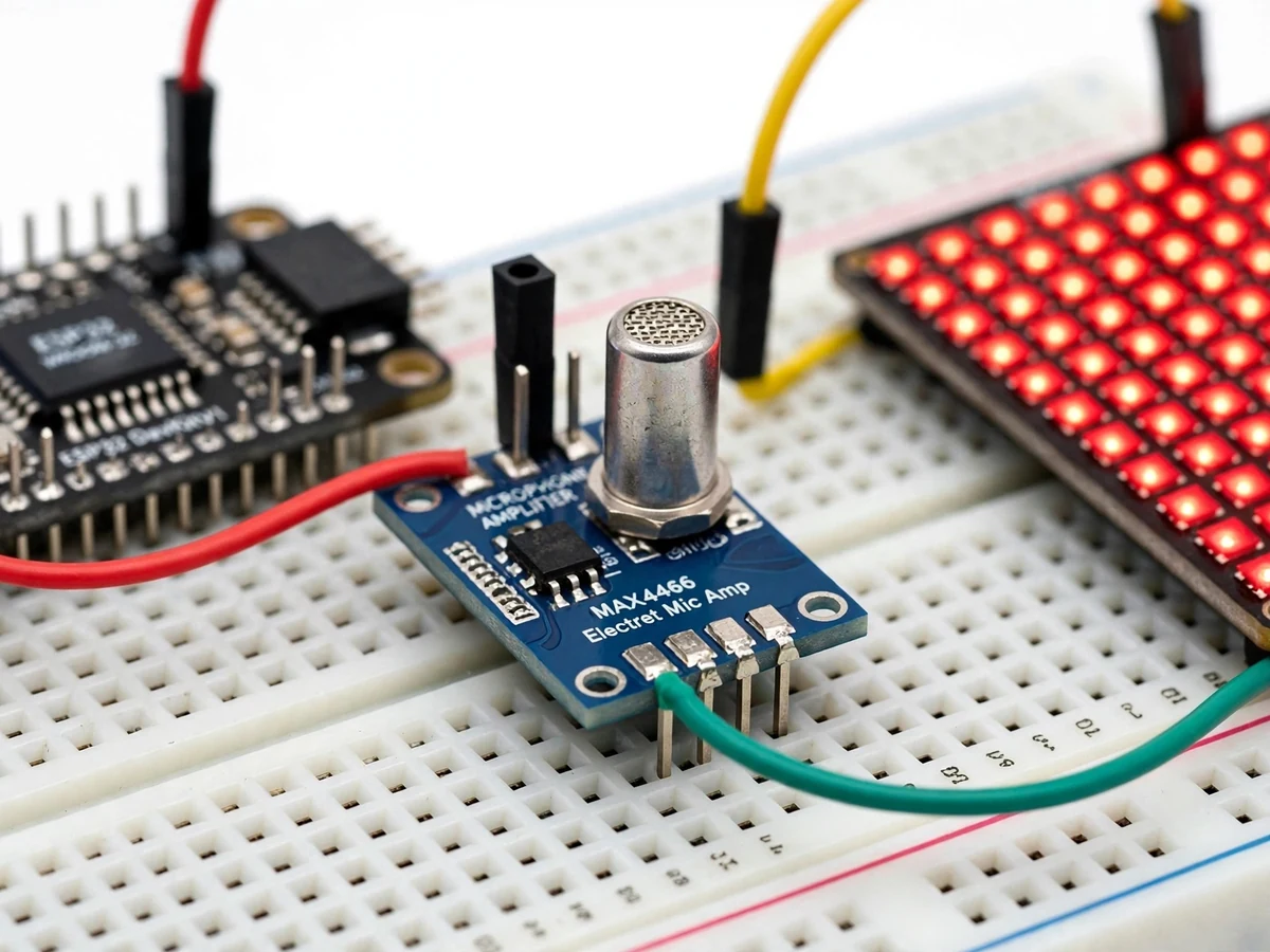
- Assembled and tested prototype (ESP32 + MAX4466 module + LED alert board on breadboard)
- Complete firmware source (Arduino IDE, C++)
- Wiring diagram and component list
- Single-point dB calibration procedure (phone SPL meter method)
- Web dashboard file (live gauge, chart, alert log)
- Project report PDF (background, circuit design, dB-mapping method, calibration, methodology)
- PPT presentation for final review
- Viva Q&A preparation document (ADC sampling, log-scale mapping, MQTT, threshold logic)
Limitations & prerequisites
- The unit is not a certified sound-level meter — absolute dB accuracy depends entirely on the buyer's one-time calibration against a phone SPL meter; uncalibrated, the board shows relative loudness bands only.
- The electret capsule hears everything, including ceiling fans and HVAC hum — the 3-second persistence filter cuts false alerts from transients but cannot remove a raised ambient floor; set thresholds above the room's background level.
- Local sensing and the LED board run fully offline, but cloud logging and the dashboard need Wi-Fi; readings taken during an outage are not backfilled in the base build.
- The base build is 5 V USB powered with no battery backup — a power cut blanks the board.
- The dashboard shows the most recent 60 seconds; long-term history needs a database, offered as an optional add-on.
- The prototype ships on breadboard as photographed; a wall-mount enclosure is not included in the base build.
Frequently Asked Questions
Is this project suitable for a final-year project?
Yes — for Electronics/E&TC, Electrical, Computer Science and IoT programs. It demonstrates sensor interfacing, ADC sampling, log-scale signal mapping, threshold logic with a persistence filter, Wi-Fi/MQTT communication and a working web dashboard: a complete hardware-to-cloud story that is easy to defend in a viva.
Is it a real sound-level meter?
No — it is an academic prototype, not a certified SPL meter. The MAX4466 module measures relative sound amplitude; the firmware maps it to decibels on a log scale anchored by a one-time calibration against a phone SPL meter at 1 m. Calibrated it reads plausibly in dB; uncalibrated, treat the board as relative loudness bands.
What exactly happens when the classroom gets too loud?
When the level stays above the 70 dB threshold (design target) for 3 sustained seconds, the 8×8 matrix scrolls "TOO LOUD" in the red zone, the tri-color strip turns red, and the dashboard writes a timestamped alert entry. Brief spikes — a dropped book, a single clap — are deliberately ignored by the persistence filter.
Does it work without Wi-Fi?
Yes, locally. Sensing, the LED alert board and the threshold logic run entirely on the ESP32 with no network needed. Only the cloud logging and the web dashboard pause without Wi-Fi, and both resume automatically when the network returns. Readings taken during an outage are not backfilled in the base build.
Can the threshold and alert style be changed?
Yes — both are configurable, not fixed. The alert threshold, the 55 dB zone boundary and the 3-second persistence time are firmware constants and dashboard settings, and the LED patterns and scroll text can be edited in the firmware. A buzzer or SMS/WhatsApp escalation is an optional add-on.
Which controller and sensor are used, and can they change?
An ESP32 DevKit reads a MAX4466 electret microphone amplifier module — the ESP32 for its 12-bit ADC and built-in Wi-Fi, the MAX4466 for its adjustable 25×–125× gain. A cheaper LM393 sound-detection module can be fitted, but it only gives a digital loud/not-loud output with no dB readings, so it is a downgrade, not a swap.
Components & software requirements
- ESP32 (dual-core 240 MHz · 12-bit ADC)
- MAX4466 electret microphone amplifier module
- 8×8 LED matrix (MAX7219) · tri-color zone LEDs
- Arduino IDE (C++ firmware)
- MQTT (cloud logging)
- HTML · CSS · JavaScript (web dashboard)
- Solderless breadboard prototyping
- USB 5 V power
Delivery information
Built-to-order project. Delivery timeline is shared after order confirmation based on current queue.
Support terms
Complete documentation, setup guide, and viva preparation included. Support for setup and explanation provided.
Download free synopsis (PDF)
Enter your name and WhatsApp number — the synopsis PDF downloads immediately. We may send occasional project updates on WhatsApp; no spam.