
More project photos (2)
The problem
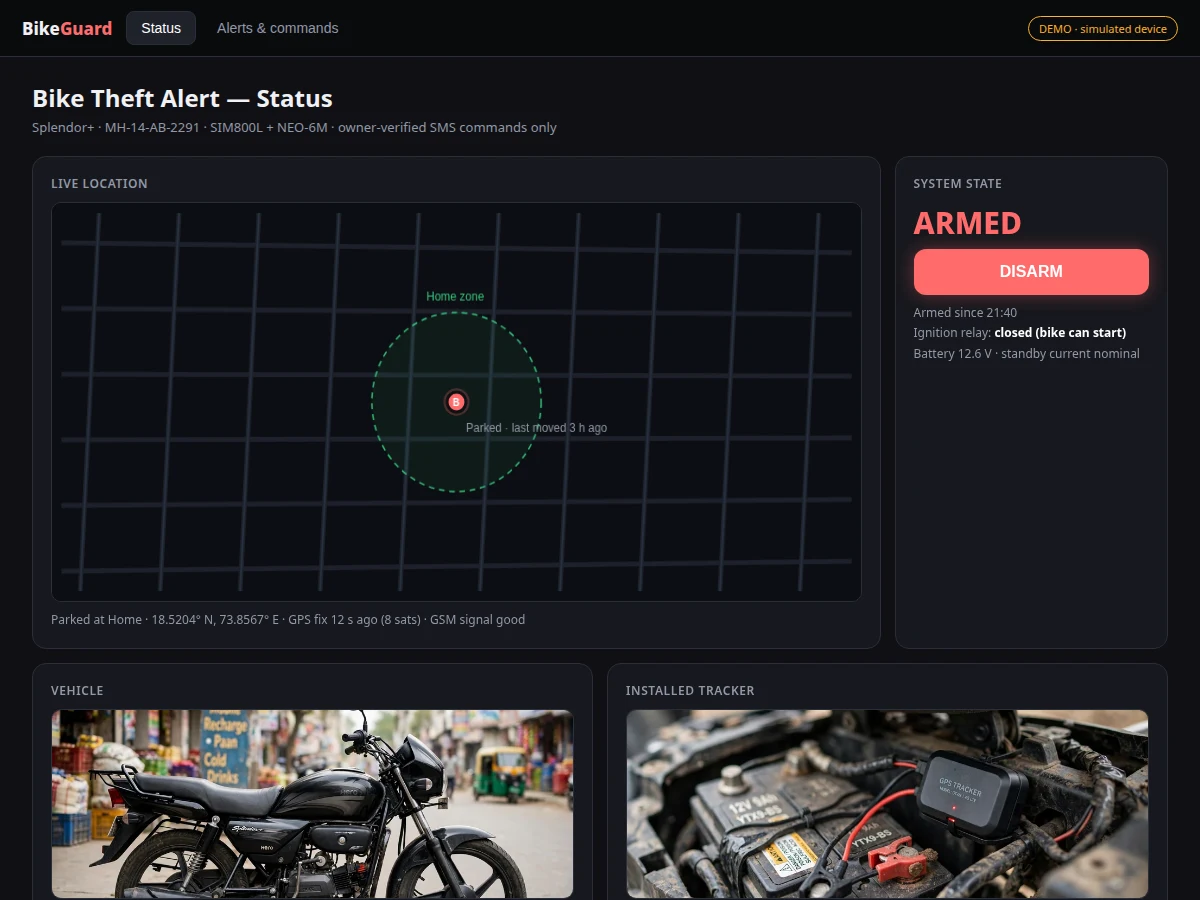
Two-wheeler theft is common and recovery rates are poor, largely because owners learn about the theft hours later with no idea where the vehicle went. Commercial GPS trackers with theft alerts exist but carry subscriptions and are closed boxes a student cannot open, modify or explain in a viva. This project builds the open version: a compact tracker hidden on the bike that detects tampering with a vibration sensor, alerts the owner by SMS with a live GPS maps link within seconds, and lets the owner immobilize the ignition remotely by SMS. An Arduino-class controller ties together the SIM800L GSM module, NEO-6M GPS receiver, vibration sensor, buzzer and an ignition-cutoff relay, all powered from the bike's 12 V battery with a low-power armed state. The companion dashboard shows the bike's location, arm/disarm state and a full alert history — so the report documents a complete security loop from sensor to phone to dashboard.
How it works
- With the system armed, the vibration sensor is sampled continuously; sustained vibration above the threshold counts as a tamper event (a single sensitivity setting filters out passing-traffic rumble).
- On tamper, the controller wakes the GPS receiver, waits for a fix (cold start typically under ~30 s with clear sky), and reads the coordinates.
- The SIM800L sends an SMS to the registered owner number with the coordinates formatted as a maps link, then sounds the on-board buzzer.
- If the bike keeps moving, follow-up SMS updates with fresh coordinates are sent at the configured interval while the alert is active.
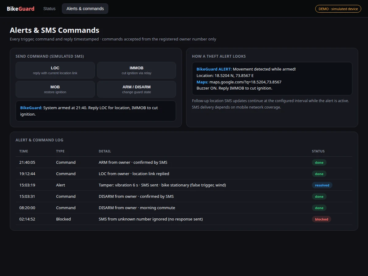
- The owner can reply IMMOB to open the ignition-cutoff relay (engine cannot start), MOB to restore it, LOC for the current position, ARM/DISARM to change state.
- Every event and command is logged with timestamps to the dashboard over GPRS, which renders the alert history and live map.
- Incoming SMS commands are parsed only if they come from the registered owner number; all others are ignored silently.
Tech stack:
- Arduino-class controller (Arduino-core firmware)
- SIM800L GSM module (SMS + GPRS) with antenna
- NEO-6M GPS receiver with antenna
- SW-420 vibration sensor module (sensitivity adjustable)
- Ignition-cutoff relay module + buzzer
- Bike 12 V battery power with low-power armed standby
- Web dashboard (live map, arm/disarm, alert log)
| Parameter | Value |
|---|---|
| Controller | Arduino-class board, Arduino-core firmware |
| GSM | SIM800L quad-band; SMS alerts and commands, GPRS for dashboard sync |
| GPS | NEO-6M receiver; cold-start fix typically under ~30 s with clear sky |
| Tamper sensing | SW-420 vibration module, sensitivity trimmer |
| Immobilizer | Relay in ignition circuit, SMS-controlled with safety interlock notes |
| Power | Bike 12 V battery; low-power sleep in armed standby |
| Command set | ARM, DISARM, LOC, IMMOB, MOB (owner number only) |
| Alert latency | SMS sent within seconds of trigger, subject to network and GPS fix time |
| Dashboard | Live map, arm/disarm toggle, timestamped alert/command log |
| SIM requirement | Active SIM with SMS balance; 2G/GPRS coverage needed (carrier-dependent) |
Project features
- [Tamper SMS alert] Vibration above the armed threshold triggers an SMS within seconds carrying the GPS coordinates as a tappable maps link.
- [Live location on demand] The owner texts a command (e.g. LOC) and receives the current position link anytime; the dashboard shows the bike on a live map.
- [Remote immobilizer] An SMS command drives the relay to cut the ignition circuit; a second command restores it — documented with wiring and safety notes.
- [Arm/disarm by SMS] Arm and disarm remotely by texting commands, with confirmation SMS; a dashboard toggle mirrors the state.
- [Buzzer deterrent] On-board buzzer sounds on tamper while armed, drawing attention at the scene in addition to the silent SMS.
- [Alert log] Every arming, trigger, SMS command and location reply is timestamped in the dashboard's alert history.
- [Low-power armed state] The controller sleeps between sensor checks on armed standby to avoid draining the bike battery; GPS powers up on trigger and on demand.
- [Owner-number lock] Only the registered owner number's SMS commands are accepted; unknown numbers get no response.
What is included
- Assembled tracker unit (controller, SIM800L, NEO-6M, vibration sensor, relay, buzzer, wiring)
- Complete firmware (tamper detection, SMS engine, GPS handling, command parser, power management)
- Bike wiring and concealment guide (12 V tap, ignition relay wiring, safe mounting points)
- SMS command reference card for the owner
- Web dashboard (live map, arm/disarm, alert log)
- Project report PDF (background, system design, power budget, evaluation method)
- PPT presentation for final review
- Viva Q&A preparation document (GSM AT commands, GPS, relays, power management, security limits)
- Setup guide (SIM provisioning, owner-number registration, sensitivity tuning, first alert test)
Limitations & prerequisites
- SMS delivery depends on the mobile network — alerts can be delayed or lost in poor coverage, and the report states this dependency openly.
- GPS needs sky view: in basements, covered parking or dense urban canyons the fix degrades or fails, delaying the location in the alert SMS.
- The SIM800L is a 2G module — the buyer must confirm 2G/GPRS availability on their carrier; dashboard sync needs data while SMS needs only the GSM network.
- The ignition-cutoff relay must be wired per the safety notes (fail-safe orientation documented); incorrect wiring can prevent starting or cut the engine unexpectedly.
- A determined thief who finds and removes the unit defeats it — concealment guidance is included, but no tracker is theft-proof and the report says so.
- Armed standby draws a small current continuously; on a weak bike battery over many idle days this matters, and the power budget section quantifies it.
Frequently Asked Questions
How fast is the theft alert?
The SMS is composed and sent within seconds of a confirmed tamper trigger, but total time depends on getting a GPS fix (typically under ~30 s cold start with clear sky) and the mobile network.
How does the owner get the location?
As a tappable maps link inside the SMS, plus live on the dashboard map. Texting LOC anytime returns the current position the same way.
What does the remote immobilizer do?
The IMMOB command opens a relay in the ignition circuit so the engine cannot start; MOB restores it. Wiring and fail-safe orientation are covered in the installation guide.
Can someone else control it by SMS?
No — commands are accepted only from the registered owner number; messages from any other number are ignored.
Will it drain my bike battery?
Armed standby uses a small sleep current documented in the power budget; it is designed for normal daily-use bikes, with a caution for long idle parking on weak batteries.
Is this project suitable for a final-year project?
Yes — for Electronics, Electrical and IoT programs. It demonstrates GSM AT-command control, GPS interfacing, sensor debouncing, relay driving, low-power design and a real security application, all strong viva material. Suitable for B.E./B.Tech final-year projects in Electronics, Electrical and IoT.
Components & software requirements
- Arduino-class controller (Arduino-core firmware)
- SIM800L GSM module (SMS + GPRS) with antenna
- NEO-6M GPS receiver with antenna
- SW-420 vibration sensor module (sensitivity adjustable)
- Ignition-cutoff relay module + buzzer
- Bike 12 V battery power with low-power armed standby
- Web dashboard (live map, arm/disarm, alert log)
Delivery information
Built-to-order project. Delivery timeline is shared after order confirmation based on current queue.
Support terms
Complete documentation, setup guide, and viva preparation included. Support for setup and explanation provided.