
More project photos (2)
The problem
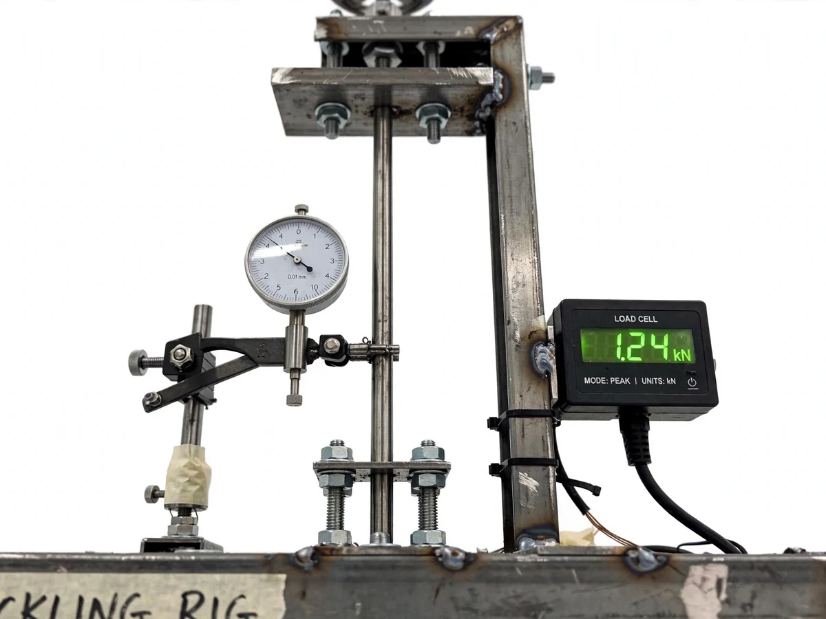
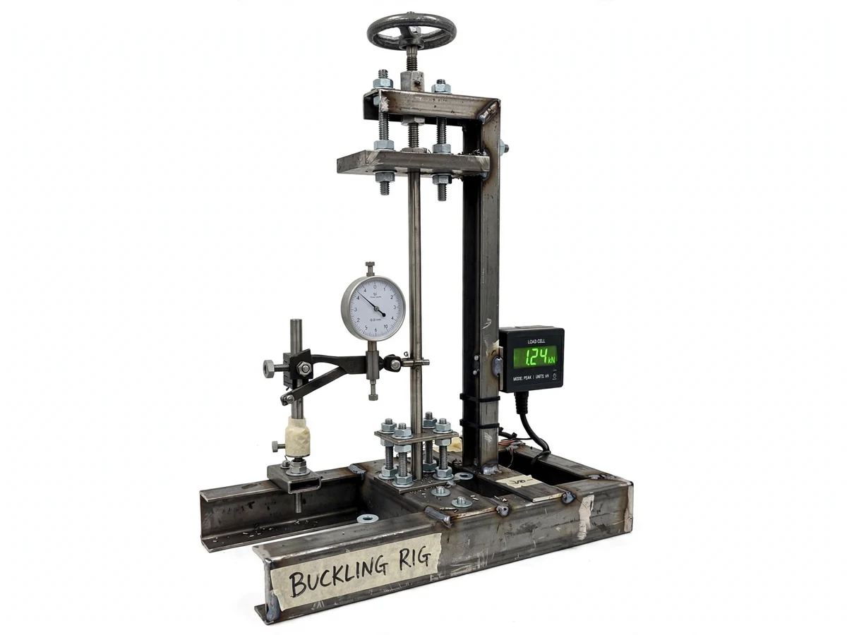
Euler's buckling formula is derived in every strength-of-materials course, but few students ever watch a column buckle. Commercial universal testing machines are expensive, shared across departments, and perpetually booked — so the experiment stays theoretical. This project brings it to the student's own bench: a rigid welded-steel frame with a hand-operated screw jack loads slender steel columns axially until lateral buckling sets in. An S-type load cell in the load path drives a digital indicator (no more squinting at analog dials), and a 0.01 mm dial gauge on a magnetic stand tracks mid-height deflection — the tell-tale signal that stays near zero until the critical load, then takes off. With interchangeable end fixtures for pinned–pinned, fixed–free and fixed–fixed conditions, the rig turns the abstract effective-length factor K into something you can feel in the hand wheel.
How it works
- The column specimen is seated between the lower platen and loading head with the chosen end fixtures.
- The dial gauge is positioned at mid-height and zeroed; the load indicator is zeroed with no load.
- The hand wheel drives the screw jack, applying axial load in small increments.
- At each step, the operator records load (digital display) and lateral deflection (dial gauge).
- Deflection stays near zero until the critical load, then increases rapidly — the buckling point.
- The experimental critical load is read off and compared with P_cr = π²EI/(KL)² for the tested end condition.
Tech stack:
- Mild steel fabrication (welded channel frame)
- S-type load cell · 5 kN with digital indicator
- Dial gauge · 0.01 mm least count, magnetic stand
- Hand-operated screw jack loading
- Interchangeable end fixtures (pinned/fixed)
- Euler buckling theory (analysis)
- Spreadsheet recording template
- Calibration procedure documentation
| Parameter | Value |
|---|---|
| Rig type | Benchtop axial compression, manual loading |
| Load cell | S-type, 5 kN capacity (design target) |
| Readout resolution | 1 N (design target) |
| Dial gauge | 0.01 mm least count, magnetic stand |
| End conditions | Pinned–pinned, fixed–free, fixed–fixed |
| Specimens | Slender mild-steel columns, multiple slenderness ratios |
| Frame | Welded steel channel, benchtop footprint |
| Loading | Hand-operated screw jack |
| Theory reference | Euler: P_cr = π²EI/(KL)² |
| Calibration | Buyer-run zero/span procedure supplied |
Project features
- [Rigid loading frame] Welded steel channel construction, sized an order of magnitude stiffer than specimens so machine compliance stays negligible.
- [Digital load readout] S-type load cell with digital indicator in the load path (design target: 0–5 kN range, 1 N resolution).
- [Interchangeable end fixtures] Pinned–pinned, fixed–free and fixed–fixed setups, machined for repeatable end conditions.
- [Dial gauge deflection] 0.01 mm least-count gauge on a magnetic stand positioned at mid-height, the classic buckling signal.
- [Specimen set] Slender mild-steel columns in multiple slenderness ratios for a full experimental series.
- [Calibration procedure] A documented buyer-run procedure to zero and span-check the load readout on the student's own build.
- [Recording template] Spreadsheet template for load–deflection pairs and Euler-prediction comparison tables.
What is included
- Fabricated buckling test rig (frame, screw jack, fixtures)
- S-type load cell with digital load indicator
- Dial gauge with magnetic stand
- Specimen set (slender steel columns)
- Fabrication drawings and assembly guide
- Calibration and test procedure document
- Load–deflection recording spreadsheet template
- Project report PDF (theory, design calculations, methodology)
- PPT presentation and viva Q&A
Limitations & prerequisites
- Load-cell range and resolution are design targets from component datasheets, confirmed during the buyer's calibration — not certified figures.
- The rig is an educational test setup, not a certified universal testing machine; results are for coursework, not commercial certification.
- Manual loading means strain rate is operator-dependent; a motorized drive is future scope.
- Specimen straightness and end-fixture seating affect results — the procedure documents how to minimize this.
- No measured test figures are claimed before the rig is built and calibrated by the buyer.
Frequently Asked Questions
What does the rig actually demonstrate?
That a slender column fails by lateral buckling at a critical axial load far below its compressive strength — and that the critical load changes dramatically with end conditions, exactly as Euler predicts.
How is the critical load identified?
From the load–deflection curve: deflection stays near zero, then takes off at buckling. The take-off load is the experimental critical load, compared against π²EI/(KL)².
Why a digital load readout instead of a dial?
Precision and readability — 1 N resolution with no parallax error — and it makes the load–deflection recording far less error-prone for students.
Which end conditions can be tested?
Pinned–pinned, fixed–free and fixed–fixed, via interchangeable fixtures. Each changes the effective length factor K (1.0, 2.0, 0.5), giving three distinct theoretical predictions to verify.
Is the rig safe to operate?
Yes — loads are small, loading is manual and slow, and the procedure includes safe specimen handling. It is a benchtop educational rig, not a high-energy press.
Is this project suitable for a final-year project?
Yes — for Mechanical Engineering programs. It combines machine design, fabrication, instrumentation and theory validation in one hands-on build. Suitable for B.E./B.Tech final-year projects in Mechanical Engineering.
Components & software requirements
- Mild steel fabrication (welded channel frame)
- S-type load cell · 5 kN with digital indicator
- Dial gauge · 0.01 mm least count, magnetic stand
- Hand-operated screw jack loading
- Interchangeable end fixtures (pinned/fixed)
- Euler buckling theory (analysis)
- Spreadsheet recording template
- Calibration procedure documentation
Delivery information
Built-to-order project. Delivery timeline is shared after order confirmation based on current queue.
Support terms
Complete documentation, setup guide, and viva preparation included. Support for setup and explanation provided.