
More project photos (2)

The problem
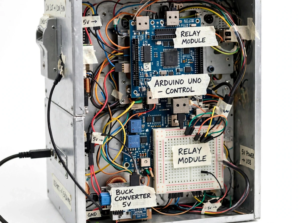
The Coin-Operated Mobile Charging Station with Timer Display and Multi-Port Output is a public coin-operated charging kiosk that sells charging time, not a fixed charge, and makes the remaining time visible at all times. A user inserts a physical coin, the coin acceptor checks it, and the controller starts a countdown that is shown on a four-digit timer display while the USB ports stay powered. When the countdown reaches zero, the controller switches the USB rail off, so the session ends cleanly without anyone having to unplug a cable or watch a clock. It suits waiting areas where people carry a low phone battery and no spare socket. It combines coin validation, timekeeping, display driving, relay switching, and regulated low-voltage power in one compact build. The prototype uses physical coins only, with no payment-gateway or real-station integration, and the minutes-per-coin rate is set by the administrator in firmware.
Acceptor checks the coin and sends pulses.
Follow the working sequence
How it works
The Coin-Operated Mobile Charging Station with Timer Display and Multi-Port Output works as a closed loop from coin to cutoff, with the controller in the middle of every decision. An inserted coin reaches the acceptor, which validates it and reports the result as pulses. The Arduino Uno counts those pulses, converts the accepted coin into session minutes using the configured rate, and starts or extends a countdown timer. While the timer is running, the controller holds the relay closed, the buck converter supplies regulated 5 V to the USB ports, and the display shows the time left, second by second. If another valid coin arrives mid-session, its minutes are added to the remaining time. When the countdown reaches zero, the controller opens the relay, the USB rail goes dead, and the display returns to zero, ready for the next user. No app, network connection, or payment gateway is involved at any point.
- The user inserts a physical coin into the CH-926 coin acceptor, which validates the coin by its size and material response and either accepts it or returns it.
- For each accepted coin, the acceptor sends a pulse signal on its output wire, and the Arduino Uno counts the pulses on an interrupt pin so no coin is missed while the display updates.
- The controller converts the counted pulses into session minutes using the admin-configured minutes-per-coin rate and adds that time to the remaining countdown.
- The controller closes the relay, connecting the regulated 5 V USB rail, and starts the countdown on the four-digit timer display in minutes and seconds.
- Phones plugged into any of the four USB-A ports charge from the shared regulated rail while the countdown runs, and the display ticks down once per second.
- Any further accepted coin during the session adds its configured minutes to the remaining time, and the display immediately shows the new total.
- When the countdown reaches zero, the controller opens the relay, the USB rail switches off, and the display returns to zero for the next user.
Builder note: the acceptor must be taught with more than 15 sample coins of each denomination before first use, and the pulse count for each coin must be checked on the bench after any reset, because a reset acceptor can return zero pulses until its pulse setting is restored. That bench check, not the coin slot alone, is what makes the timer trustworthy.
Tech stack:
- Arduino Uno (ATmega328P)
- CH-926 multi-coin acceptor
- TM1637 four-digit timer display
- LM2596 buck converter module
- 5 V relay module for USB rail switching
- USB-A charging ports
- Arduino IDE firmware
- 12 V DC adapter supply
| Parameter | Value |
|---|---|
| Controller | Arduino Uno with ATmega328P at 16 MHz clock speed (datasheet value) |
| Controller logic | 5 V logic with 20 mA recommended current per I/O pin (datasheet value) |
| Coin acceptor | CH-926 multi-coin acceptor at 12 V DC supply (datasheet value: 12 V ± 10%) |
| Coin acceptor current | 65 mA current draw (datasheet value: 65 mA ± 5%) |
| Accepted coin size | Diameter 15 mm to 32 mm and thickness 1.2 mm to 3.4 mm (datasheet value) |
| Coin recognition time | 0.6 seconds maximum per coin (datasheet value) |
| Timer display | TM1637 four-digit display at 5 V supply (design value) |
| USB output | 5 V DC regulated output (design target) |
| USB ports | 4 ports of USB-A type (design value) |
| USB current budget | 2 A continuous total across all ports (design budget for the LM2596 module) |
| Relay switching | Low-voltage 5 V USB rail only with mains never switched by the relay (safety design rule) |
| Input supply | 12 V DC adapter supply (design value) |
| Minutes per coin | Configurable in firmware as a design target with no fixed tariff claimed |
Project features
The Coin-Operated Mobile Charging Station with Timer Display and Multi-Port Output is built around four capabilities that define the whole kiosk: physical coin validation through a programmable acceptor, a visible countdown that the user can trust, four USB charging ports served from one regulated rail, and a controller that starts and ends each session without manual intervention. Coin validation keeps rejected coins out of the session logic, so only an accepted coin adds time. The countdown display is the user-facing contract of the machine, showing exactly how much paid time remains. Multi-port output lets several phones share one kiosk, while the single relay-switched rail keeps the power design simple and testable. Together these capabilities produce a machine that can be demonstrated end to end in a viva: insert a coin, watch the timer start, charge a phone, and watch the rail switch off at zero.
- [Coin validation and pulse counting] (Implemented) The CH-926 multi-coin acceptor checks each inserted coin by size and material response and sends a pulse signal to the controller for every accepted coin, while rejected coins are returned without adding time.
- [Countdown timer display] (Implemented) A four-digit seven-segment display shows the remaining session time in minutes and seconds, counts down once per second, and returns to zero when the session ends.
- [Multi-port USB charging output] (Implemented) Four USB-A ports share one regulated 5 V rail, so several phones can charge from the same kiosk during one session, within the shared current budget stated in the specifications.
- [Relay-switched USB rail] (Implemented) A relay module connects and disconnects only the low-voltage 5 V USB rail under controller command, so power starts with an accepted coin and stops automatically at the end of the countdown.
- [Regulated low-voltage power] (Implemented) An LM2596 buck converter steps the 12 V DC adapter input down to a regulated 5 V output for the USB ports, keeping the phone-side supply separate from the coin acceptor supply.
- [Session top-up by extra coins] (Implemented) Additional accepted coins during a running session add their configured minutes to the remaining time, and the display updates to the new total immediately.
- [Configurable minutes-per-coin rate] (Configurable) The minutes added per accepted coin are set in firmware by the administrator, so the same hardware can be demonstrated with different session lengths; the rate shown in the photographs is an illustration, not a tariff.
- [Coin-box total display] (Future scope, not included) A future version could show a cumulative coin count or total collected value on a second display, but that readout is not part of the base build and must not be described as included.
What is included
- Assembled coin-operated charging kiosk prototype with coin acceptor, timer display, and four USB ports
- Arduino firmware source code with pulse counting, countdown timing, relay control, and configurable minutes-per-coin rate
- Circuit diagram and wiring documentation for the acceptor, controller, display, relay, and buck converter
- Component list with part numbers and datasheet values for the controller, acceptor, display, and regulator
- Coin-acceptor calibration procedure covering sample coins, pulse settings, and bench verification
- Project report PDF (background, design, methodology, safety notes, and limitations)
- PPT presentation for final review
- Viva Q&A preparation document (coin validation, interrupts, timers, relays, and regulated power)
Limitations & prerequisites
- The prototype accepts physical coins only; no card, wallet, UPI, or payment-gateway payment is implemented, and none is claimed.
- Charging speed depends on the connected phone and cable; the 2 A total budget is shared across all 4 ports, so four phones charging together each receive less current than one phone alone.
- The coin acceptor must be calibrated for the exact coins used; an uncalibrated or reset acceptor can reject valid coins or report zero pulses, so the bench check in the calibration procedure is mandatory.
- The kiosk is an academic prototype, not a certified commercial vending machine; it has no tamper-proof cash box, no coin-count audit, and no weatherproofing for outdoor installation.
- The USB rail carries standard 5 V charging only; fast-charging protocols and USB-C Power Delivery negotiation are not implemented.
- Mains safety depends on the external 12 V adapter and the enclosure fuse; the prototype must not be opened while powered, and mains wiring must never be routed through the relay.
Frequently Asked Questions
Which controller and coin acceptor are used?
The controller is an Arduino Uno based on the ATmega328P, and the coin acceptor is a CH-926 multi-coin acceptor. The Uno counts acceptor pulses on an interrupt pin, runs the countdown, drives the timer display, and switches the USB rail relay. The CH-926 runs from a 12 V DC supply and reports each accepted coin as pulses.
How does the timer work, and what happens when time runs out?
An accepted coin starts or extends a countdown shown in minutes and seconds on the four-digit display, and the USB rail stays powered while time remains. Extra coins inserted during a session add their configured minutes to the remaining time. When the countdown reaches zero, the controller opens the relay and the USB rail switches off.
Is this project suitable for a final-year project?
Yes, it fits final-year work in Electronics and Telecommunication because it combines coin validation, interrupt-based pulse counting, timer programming, display driving, relay switching, and regulated power in one demonstrable machine. The build gives clear viva material on embedded control and power design.
Can the minutes-per-coin rate be changed?
Yes, the minutes added per accepted coin are an admin-configured value in the firmware, so the same hardware can be demonstrated with different session lengths. Changing the rate needs a firmware edit and a bench test, not a hardware change. The rate is a design setting, never a claimed commercial tariff.
Is the kiosk safe to use with phones and mains power?
The design keeps mains away from the switching path: an external 12 V adapter provides isolation, a fuse protects the input, and the relay switches only the low-voltage 5 V USB rail. Phones therefore never meet mains voltage through the kiosk, but the enclosure must stay closed while powered.
Can more ports or different connectors be added?
Yes, extra USB-A ports can be added on request, but the 2 A total current budget stays shared, so more ports do not increase total charging power. USB-C connectors or a second regulated rail are possible customizations, subject to a revised power budget and retesting before delivery.
Components & software requirements
- Arduino Uno (ATmega328P)
- CH-926 multi-coin acceptor
- TM1637 four-digit timer display
- LM2596 buck converter module
- 5 V relay module for USB rail switching
- USB-A charging ports
- Arduino IDE firmware
- 12 V DC adapter supply
Delivery information
Built-to-order project. Delivery timeline is shared after order confirmation based on current queue.
Support terms
Complete documentation, setup guide, and viva preparation included. Support for setup and explanation provided.
Download free synopsis (PDF)
Enter your name and WhatsApp number — the synopsis PDF downloads immediately. We may send occasional project updates on WhatsApp; no spam.