
More project photos (2)
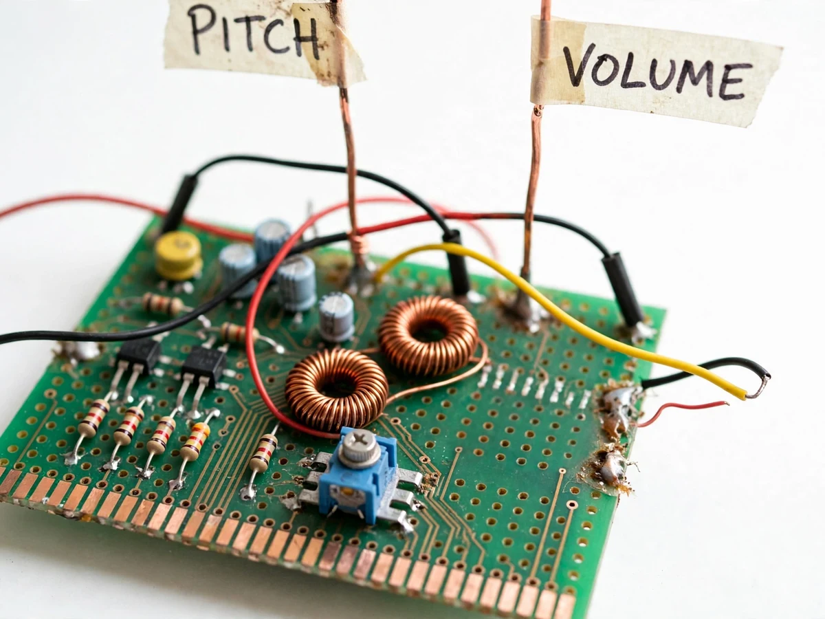
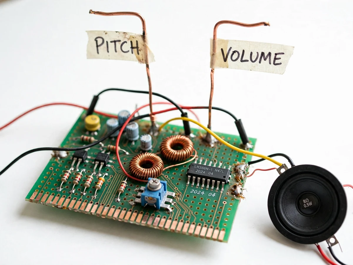
The problem
The theremin is the only musical instrument played without physical contact — the player's hand position near two antennas sets the pitch and the volume. It is also the most physical demonstration of the heterodyne principle taught in analog electronics: two radio-frequency oscillators (here near 440 kHz) are mixed, and their difference frequency becomes the audible note. Most students meet oscillators and mixers only as equations and simulation waveforms, while the commercial theremin kits that exist arrive as finished boxes that hide the circuitry. This project closes that gap by building the instrument from discrete stages on a homemade Veroboard-style PCB: a fixed reference oscillator, a variable pitch oscillator whose tank-circuit capacitance is pulled by the hand near the pitch antenna, a mixer that outputs the beat frequency, a volume-antenna control stage, and an LM386 audio amplifier driving a speaker. Calibrating the instrument — trimming the reference oscillator so the beat nulls with the hand far away, then checking pitch tracking across the playing zone — turns LC resonance and heterodyne mixing from theory into a tuned, playable result.
How it works
- Two LC transistor oscillators are built to run near 440 kHz: a fixed reference oscillator and a variable oscillator whose tank circuit includes the pitch antenna.
- With the hand held far from the pitch antenna, the reference oscillator's trimmer is adjusted until its frequency matches the variable oscillator — the mixer output (beat) drops to near zero, the "null" point.
- Bringing the hand toward the pitch antenna adds body capacitance to the tank, pulling the variable oscillator's frequency down; the mixer outputs the difference frequency, which rises and falls as the audible pitch.
- The volume antenna's circuit converts the other hand's distance into a control level that gates the audio path — hand close quiets the note, hand withdrawn lets it sing.
- The resulting beat signal passes through the volume stage into the LM386 amplifier, whose gain is set for clean, undistorted drive of the 8-ohm speaker.
- The filtered 12 V supply with stage decoupling keeps both RF oscillators stable, so the pitch does not drift with mains ripple or loading changes during play.
Tech stack:
- Discrete transistor LC oscillators (Colpitts-type)
- Diode mixer / beat-frequency stage
- LM386 audio power amplifier
- Copper-rod pitch and volume antennas
- RC and LC supply filtering
- Veroboard-style hand-built PCB
- Oscilloscope / DSO for calibration
- 12 V DC adapter
| Parameter | Value |
|---|---|
| Oscillator frequency | Approximately 440 kHz per oscillator (design) |
| Audio (beat) output range | Approximately 0–3 kHz difference (design target, set during calibration) |
| Amplifier | LM386, gain set approximately 20–200 per datasheet (build-configured) |
| Speaker | 8 Ω, approximately 0.5 W (expected) |
| Power supply | 12 V DC adapter with filtering (expected) |
| Antennas | Copper rod, approximately 30–40 cm (design) |
| Pitch null point | Set by buyer-run trimmer procedure (not a measured spec) |
| PCB | Single-sided Veroboard-style, approximately 15 × 10 cm (design) |
Project features
- [Dual RF heterodyne oscillator pair] Two transistor LC oscillators run near 440 kHz — one fixed reference, one variable with the pitch antenna forming part of its tank capacitance. A mixer stage outputs the difference (beat) frequency, which is the audible note the player hears.
- [Contactless pitch control] Moving a hand near the copper-rod pitch antenna adds body capacitance to the tank circuit, pulling the variable oscillator's frequency and shifting the beat note — the instrument is played entirely without touch.
- [Volume antenna stage] A second copper-rod antenna feeds a volume-control circuit that converts hand distance into a varying audio level, so loudness is shaped gesturally just like pitch.
- [LM386 audio amplifier] The low-level beat signal is boosted by an LM386 power-amplifier stage with onboard gain and volume controls, driving the 8-ohm speaker at clear room-filling levels.
- [Trimmer-based pitch calibration] A trimmer in the reference oscillator nulls the beat frequency with the hand held far from the pitch antenna; the documented buyer-run procedure then sets the playing range and checks pitch tracking across the hand zone.
- [Filtered, decoupled power supply] A 12 V DC adapter feeds the RF stages through filtering and per-stage decoupling, so supply ripple and mains hum do not modulate the oscillators or bleed into the audio output.
- [Hand-built copper antennas] The pitch and volume antennas are hand-bent copper rods mounted on the enclosure with proper grounding, giving the instrument its classic theremin silhouette and stable capacitive fields.
- [Oscilloscope test points] Labeled test points at the reference oscillator, variable oscillator and mixer output let the student observe every stage on a CRO or DSO while calibrating — strong material for the viva demonstration.
What is included
- Working theremin prototype (oscillator/mixer board, pitch and volume antennas, LM386 amplifier, speaker, enclosure)
- Circuit diagrams and wiring documentation
- Complete component list with values
- Trimmer calibration procedure guide
- Project report PDF (theory, design calculations, build steps, calibration log template)
- PPT presentation for final review
- Viva Q&A preparation document
Limitations & prerequisites
- Monophonic single-note instrument — it cannot play chords or polyphonic parts.
- Pitch tracking depends on room capacitance and nearby objects; the null must be re-trimmed if the instrument is moved.
- Beat-frequency linearity is approximate — this is a musical instrument, not a frequency standard, and no measured accuracy is claimed.
- Oscillator stability is a design target, not a measured figure; some drift with temperature and supply variation is expected behavior.
- The LM386 stage is teaching-grade audio, not hi-fi; mild distortion at full volume is expected.
- Body capacitance differs between players, so the usable pitch range varies from person to person.
- An academic prototype, not a concert-grade instrument; stage performance is out of scope.
Frequently Asked Questions
How does the theremin produce sound without being touched?
The pitch antenna is part of an LC oscillator's tank circuit. Your hand adds capacitance as it approaches, shifting that oscillator's frequency; the mixer subtracts the fixed reference frequency and the difference — the beat — is the audible note.
Is this project suitable for a final-year project?
Yes — for Electronics, E&TC and Electrical programs. It demonstrates LC oscillator design, heterodyne mixing, capacitive sensing, audio power amplification and a real calibration procedure, all of it observable on an oscilloscope during the viva — a strong analog-electronics build rather than another microcontroller demo.
What equipment do I need to calibrate it?
A small screwdriver for the trimmer and ideally an oscilloscope or DSO to watch the oscillator and mixer test points; a digital multimeter covers the DC checks. The full step-by-step trimming procedure ships with the project.
Can the pitch range be changed?
Yes. The playing range is set by the tank-circuit component values and the reference-oscillator trim point, so it is configurable at build time; the calibration guide explains how to widen or narrow the range for the student's preference.
What are the main limitations?
It is monophonic, pitch tracking depends on the room and must be re-trimmed after moving the instrument, and oscillator stability is a design target rather than a measured spec. It is an academic prototype, not a concert instrument.
What will I receive with the project?
The working theremin prototype with antennas, amplifier and speaker, circuit and wiring documentation, the component list, the trimmer calibration guide, the project report PDF, a review PPT and a viva Q&A document — all prepared built-to-order. Suitable for B.E./B.Tech final-year projects in Electronics, E&TC and Electrical.
Components & software requirements
- Discrete transistor LC oscillators (Colpitts-type)
- Diode mixer / beat-frequency stage
- LM386 audio power amplifier
- Copper-rod pitch and volume antennas
- RC and LC supply filtering
- Veroboard-style hand-built PCB
- Oscilloscope / DSO for calibration
- 12 V DC adapter
Delivery information
Built-to-order project. Delivery timeline is shared after order confirmation based on current queue.
Support terms
Complete documentation, setup guide, and viva preparation included. Support for setup and explanation provided.