
More project photos (2)
The problem
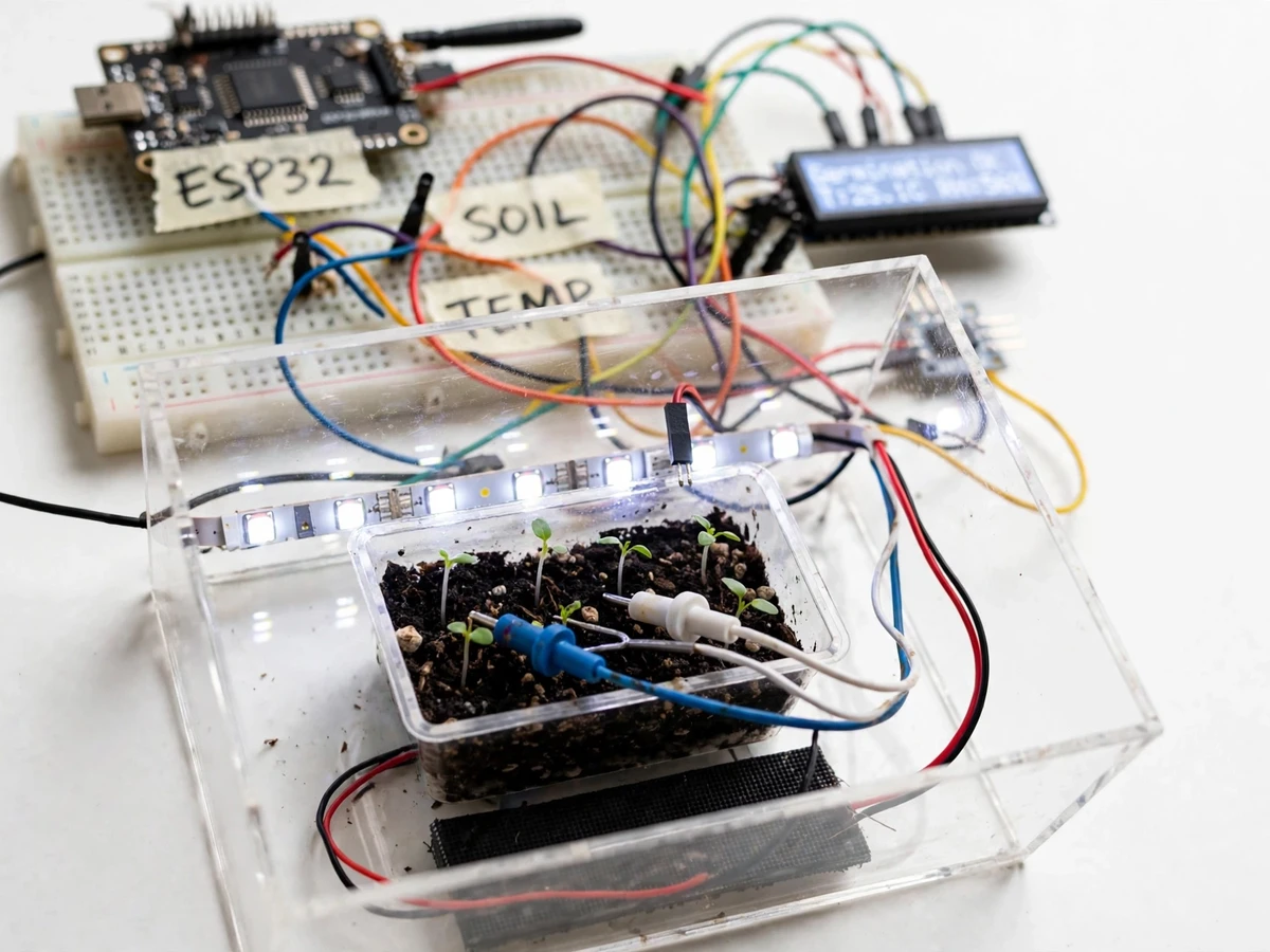
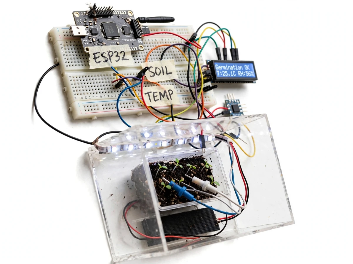
Germination fails silently. Seeds sown in a tray dry out between waterings, or sit too cold to sprout, and the student discovers the failure a week later when nothing emerges. Manual checking — a finger in the soil twice a day — misses the drying cycles that matter, and there is no record of what the tray actually experienced. This project instruments the germination tray: soil-moisture probes in the seed medium report how wet the root zone is, a DHT22 tracks the chamber's temperature and humidity, and a 16x2 LCD continuously shows the germination status with live readings. A low-power LED strip above the tray gives emerging seedlings light on a timed schedule, and the clear enclosure traps humidity while keeping the whole experiment visible. The build is honest college-prototype style — breadboard, jumper wires, handwritten labels — and every sensor reading is explainable in the viva.
How it works
- Soil-moisture probes buried in the seed tray and a DHT22 in the chamber air report to the ESP32 on a timed sampling cycle.
- Firmware converts the probe readings to moisture levels using the student's calibration and compares all three parameters against configured safe bands.
- The LCD shows the germination status with live temperature and humidity; a band violation changes the status flag.
- The LED grow-light strip switches on the configured schedule to support seedlings once they emerge.
- The clear enclosure is opened only for watering; the status display tells the student when watering is actually needed.
- All thresholds are firmware constants with documented defaults, retunable for different seed types.
Tech stack:
- ESP32 DevKit (Arduino/C++ firmware)
- DHT22 temperature/humidity sensor
- Soil-moisture probes
- 16x2 character LCD
- LED grow-light strip
- Transparent chamber enclosure
| Parameter | Value |
|---|---|
| Controller | ESP32 DevKit (design) |
| Climate sensing | DHT22, ±0.5 °C / ±2–5 %RH typical (datasheet) |
| Soil sensing | Resistive probes, calibrated by buyer procedure (design) |
| Display | 16x2 character LCD (design) |
| Grow light | Low-power LED strip on timed schedule (design) |
| Enclosure | Transparent chamber, passive humidity retention (design) |
| Supply | 5 V DC regulated (expected) |
Project features
- [Soil moisture sensing] Probes in the seed tray report root-zone moisture so the student knows exactly when the medium is drying out, instead of guessing by touch.
- [Temperature and humidity monitoring] A DHT22 tracks chamber climate against germination-friendly bands, displayed live on the LCD.
- [Germination status display] The LCD shows a plain-language status (e.g. Germination OK) with current temperature and humidity readings.
- [Timed LED grow light] A low-power LED strip over the tray supports seedlings after emergence on a configurable light schedule.
- [Clear observation enclosure] The transparent chamber holds humidity in while letting the student watch germination without opening it.
- [Threshold flagging in firmware] Configurable bands flag when temperature, humidity or soil moisture leave the safe range.
- [Probe calibration procedure] A documented soil-probe calibration routine so readings are meaningful for the student's own medium.
What is included
- Working germination chamber prototype (ESP32, DHT22, soil probes, LCD, LED strip, enclosure, seed tray)
- Arduino firmware with thresholds and light scheduling
- Wiring diagram and connection list
- Soil-probe calibration procedure
- Project report PDF, PPT presentation and viva Q&A document
Limitations & prerequisites
- Resistive soil probes corrode over weeks of wet use; readings are comparative, and the report documents the capacitive-probe upgrade as future scope.
- The chamber is a passive enclosure — it retains humidity but has no active heating or misting; climate bands are monitored, not forced.
- DHT22 accuracy is ±0.5 °C / ±2–5 %RH per its datasheet; readings are indicative.
- The LED strip is a low-power demo light, not a horticultural grow light with a specified spectrum.
- Germination results depend on seed viability and medium — the system monitors conditions, it cannot guarantee sprouting.
Frequently Asked Questions
What does the LCD actually tell me?
A plain-language germination status plus the live temperature and humidity — for example 'Germination OK, T:25.1C RH:56%'. If any parameter leaves its safe band, the status flag changes so the problem is visible without interpreting numbers.
How do the soil probes work?
Two probes in the seed medium measure how easily current passes through the soil, which rises with moisture. The student calibrates the probe in their own medium (dry vs saturated readings), and the firmware maps readings to moisture levels from that calibration.
Do the probes damage the seedlings?
No — they are small, sit at the tray edge away from the seed row, and carry only a tiny sensing current during reads. The report notes the corrosion limitation of resistive probes honestly.
Can it water the tray automatically?
Not in this build — it monitors and tells the student when watering is needed. Automatic watering is listed as future scope, deliberately kept out so the sensing and calibration story stays clean.
Which seeds is it tuned for?
Thresholds ship with defaults for common vegetable seeds and are documented firmware constants; the report explains how to retune them for other seed types.
Is this project suitable for a final-year project?
Yes — for Electronics and IoT & Embedded programs. It demonstrates multi-sensor interfacing, calibration methodology, threshold logic and a complete documented build. Suitable for B.E./B.Tech final-year projects in Electronics and IoT & Embedded.
Components & software requirements
- ESP32 DevKit (Arduino/C++ firmware)
- DHT22 temperature/humidity sensor
- Soil-moisture probes
- 16x2 character LCD
- LED grow-light strip
- Transparent chamber enclosure
Delivery information
Built-to-order project. Delivery timeline is shared after order confirmation based on current queue.
Support terms
Complete documentation, setup guide, and viva preparation included. Support for setup and explanation provided.